|
|
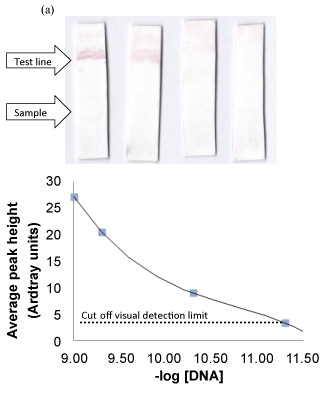
| Figure 4: Optimization of the amount of captured DNA. (a) Test strips showing subsequent dilution of DNA immobilized onto the test strip. From left, (in pmol): 1000, 500, 50 and 5. Test arrow indicates where the DNA was immobilized and sample arrow indicates where the AuNP-DNA was added. (b) Graph of the intensity of the red band in (a). The cut-off for visual detection is placed at 10 units as shown i.e., at 10 units, the red band is visually observable. |