 |
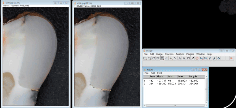
| Figure 5: Microleakage measurement using computer software Image J. The yellow line in the left picture represents the maximum penetration of the tracer. The central image exhibits the measurement of the entire cervical wall. On the right image the two length measurements are used to calculate the percentage of microleakage on dentin margin. The same procedure is realized for the enamel margins. |