 |
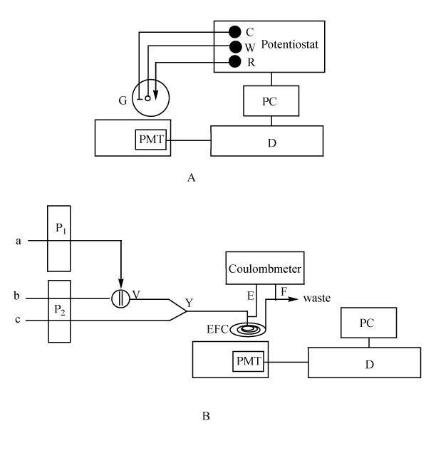
| Figure 1: The block diagram of ECL research setup (A) and ECL flow injection ECL detection setup (B). W, working electrode; R, reference electrode; C, counter electrode; G, batch ECL cell; D, CL detector; PC, computer; PMT, photomultiplier tube; P1 and P2, peristaltic pumps; V, six-way valve; Y, threeway pipe; EFC, ECL flow-through electrolysis cell; E, anode; F, cathode; a, isoniazid solution; b, NaOH solution; c, CTAB solution. |