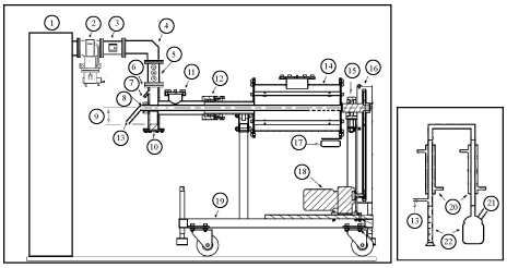
1) Generator, 2) Isolator (Circulator + Dummy load), 3) Directional coupler, 4) Bend, 5)3-stub tuner, 6) Quartz window, 7) Nitrogen inlet, 8) Central conductor, 9) Step height, 10) Step, 11) Rupture disk, 12) Gland, 13) Product outlet in microwave unit and product inlet in condensation sytem, 14) Reactor (Applicator), 15) Bearing, 16) Gear transition, 17) Wireless temperature datalogger, 18) Adjustable speed electrical machinery, 19) Stand , 20) Condensers, 21) Outlet of non-condensable gases, 22) Collection flasks.