 |
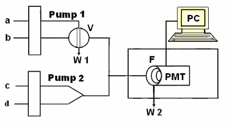
| Figure 1: Schematic diagram of flow injection CL analysis system V—sampling inlet valve; F—flowing cell: a flat spiral-coiled colorless glass tube (i.d. 1.0 mm, total diameter of the flow cell 3 cm, without gas between loops); PMT— photomultiplier tube; W—waste; a—analyte solution; b—Na2S2O3 solution; c— acidic KMnO4 solution; d—Dy3+ solution. |