|
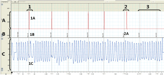
| Figure 2: Computer output from a healthy participant undertaking a descending protcol trail (protocol A) with a RK load decreasing in magnitude from 1.5 to 0.15 kPa.L.sec-1. Channel A=Participant responses to resistive load. Each spike represent the participant pushing the button in response to a perceived load applied. For RK loads 1.5 to 0.5 kPa.L.sec-1 the response is concurrent with onset of the RK load being applied. Channel B=The electronic time ‘stamps’ inserted by the researcher as each load is applied indicating its onset and magnitude. This shows the different number of breaths between each loaded phase, used to prevent any temporal awareness of loading. Channel C=The participants respiratory flow during the trial. 1=Shows a resistance of 1.5 kPa.L.sec-1 being applied; the participants response (1A), the electronic time stamp made by the researcher (1B) and the effect on respiratory flow by the application of the RK load (1C). 2=Shows an RK load of 0.3kPa.L.sec-1 being applied, showing a slightly delayed response by the participant (2A) but this occurs during the 2 breath loaded cycle and is therefore included as an accurate response. 3=Shows an RK load of 0.15 kPa.L.sec-1 being applied that is not detected by the participant. |