 |
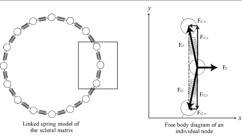
| Figure 3: Linked-spring model of the scleral matrix. The left image shows the ring of linked springs we use to model the scleral matrix. Sixteen springs are shown, but 30 nodes are used in actual modeling. The selection of 30 nodes is arbitrary, but this provides suffi cient resolution of local contours, while avoiding excessive amounts of computational complexity. The right image shows a free body diagram of one node in the linked spring model. Each node has forces Fs,1 and Fs,2 from it’s two attached springs as well as Fp, an internal ocular pressure force which acts normally to the surface. |