 |
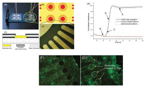
| Figure 1: Impedance-sensing device designed for cell migration assay. Left: (A) the fully assembled device consists of two chips (B) a schematic illustration of sensor electrode arrays (C) cross section of the sensor chip (D) a close-up of (B). Right: (A) The impedance variation for CaSki cells, showing the real-time progress of cell migration. (F-G) give the fluorescence image of the sensor, showing cell viability after modification of the SAMs and application of the DC current [42]. |