 |
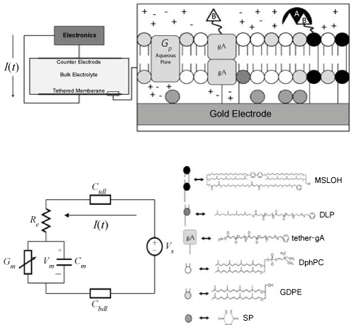
| Figure 1: Schematic, lumped circuit model, and molecular components of ICS biosensor. The “Electronics” block represents the electronic system which produces the drive potential between the electrode and counter electrode, and records the current response I(t). Gp is an aqueous pore that contributes to the equilibrium conductance of the membrane. The conducting gA dimer is shown and is composed of two gA monomers. The chemical structure of the gA dimer can be viewed in the Protein Data Bank ID: 1GRM [13]. A represents the analyte species, and B the analyte receptor. The circuit parameters are defined in the Methods and Materials section |