 |
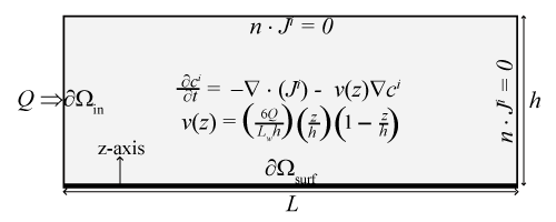
| Figure 2: Schematic of the ICS for computing the solution of (3a), (6), and (4)with boundary conditions (5). ∂Ωsurf denotes the reactive surface. The analyte enters the ICS at ∂Ωin with a flow rate of Q. Lw denotes the width of the ICS flow chamber. Other parameters are defined in Tables 1 and 2. |