 |
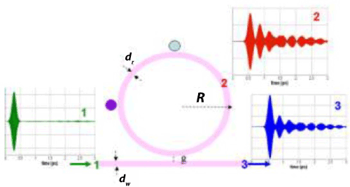
| Figure 1: Schematic of a microring sensor: a ring resonator (radius R, width dRand index nR) coupled to a waveguide (width dW, index nW). The gap between the ring and the waveguide is g. Two sensing objects (light blue and purple particles) are adjacent to the ring. Light fields are shown in time-domain for a typical simulation case: input at #1 (green), inside the cavity at #2, and output at #3 (blue). Results in frequency domain for each system under investigation will be described in the text. |