Concept of Hydrogen Redox Electric Power Generator
Received: 13-Jan-2016 / Accepted Date: 27-Jan-2016 / Published Date: 03-Feb-2016
Abstract
The hydrogen redox power generation system is a combined energy cycle consisting of the H2O=H2+1/2O2 reduction reaction performed by the bipolar alkaline water electrolyzer with electrostatic-induction potentialsuperposed electrodes and the H2+1/2O2=H2O oxidation reaction performed by the alkaline fuel cell. This type of electrolyzer functions by a mechanism in which the power used is theoretically 17% of the total electrical energy required, while the remaining 83% can be provided by electrostatic energy free of power. Part of the power delivered by the fuel cell is returned to the electrolytic cell and the remainder represents the net power output. This power generation concept assumes the use of a low temperature alkaline fuel cell and a low temperature alkaline water electrolytic cell, both commercially available. Calculations using the commercial data for the operational conditions show that the cycle power efficiencies ranging from 60 to 80% may be attainable, regardless of the total electrode surface area.
Keywords: Electric power generation; Hydrogen; Energy cycle; Fuel cell; Water electrolytic cell
18476Introduction
This review was intended to address the fundamental aspects of new high power generation system that functions with zero energy input, zero matter input and zero emissions, without any violation of the laws of thermodynamics. The method proposed and examined in the previous papers [1-4] has been termed hydrogen redox electric power generator (HRPG) and takes advantage of the intrinsic self-sustaining electrostatic energy that takes its origin from the Coulomb’s force.
Theoretical Backgrounds
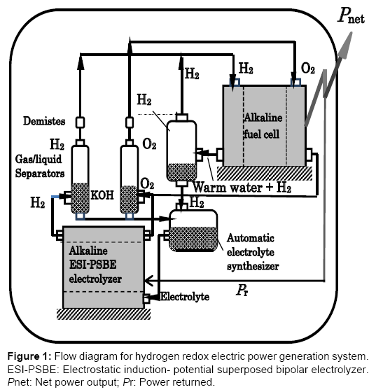
The hydrogen redox power generation system is a combined energy cycle consisting of the H2O→H2+1/2O2 reduction reaction performed by the bipolar alkaline water electrolyzer with electrostaticinduction potential-superposed electrolytic method (ESI-PSE) and the H2+1/2O2→H2O oxidation reaction performed by the alkaline fuel cell (FC). This type of electrolyzer functions by a mechanism in which the power used is theoretically 17% of the total electrical energy required, while the remaining 83% can be provided by electrostatic energy free of power. This energy was termed internally self-sustaining electrostatic energy. Part of the power delivered by the fuel cell is returned to the electrolytic cell and the remainder represents the net power output. This power generation concept assumes the use of a low temperature alkaline fuel cell and a low temperature alkaline water electrolytic cell, both commercially available. Calculations using the commercial data for the operational conditions show that the cycle power efficiencies ranging from 60 to 80% may be attainable, regardless of the total electrode surface area. Figure 1 shows a tentative plan for the hydrogen redox electric power generator. The electrolyzer is assumed to be a low temperature bipolar alkaline water electrolyzer (BAWE) and the fuel cell is a low temperature alkaline fuel cell (AFC) with the same electrolyte (H2O-30% KOH) as that for the electrolyzer. Notice that the fuel cell is situated at a higher level than the electrolyzer to use the gravitational energy to return water from the fuel cell to the electrolyzer.
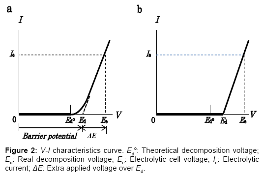
The electrostatic energy created and stored between the electrodes of an electrolytic cell is responsible for the highly positive power balance of this energy cycle. Nature of the internally self-sustaining electrostatic energy is then explained as below. The non-linear V-I characteristic curve for a practical water electrolytic cell shown in Figure 2a typically shows the amount of current measured at the point between the cell and the power supply as a function of cell voltage. In the voltage region over the theoretical decomposition voltage Ed°, the external currents in transition flow. In the consecutive region where practical electrolysis occurs, the current increases in an almost linear relationship with the applied voltage, as evidenced experimentally. To improve the energy efficiency of the electrolyzer using the ESI-PSE power supply mode, the V-I characteristics have been modified using a resistance as shown in Figure 2b. The V-I curve implies that the total cell voltage Ee, is the superposition of two separate voltages: (1) the practical decomposition voltage, Ed and (2) the additional applied voltage ΔE, which when superposed on Ed, yields the electrolytic current, Ie, and the ionic current, Iion, in the electrolyte solution. ΔE is then identified as the electromotive force (emf) for the electrolytic current, Ie. On the other hand, the ionic current in the electrolytic cell undergoing electrolysis flows by migration under the influence of the electrical potential gradient in the electrolyte solution [5]. The electronic behavior of the cell for the electrolytic decomposition of a chemically stable compound such as H2O is analogous to that of the electrical double layer capacitor for energy storage [6]. The total energy required for the cell undergoing electrolysis is the sum of the energies that correspond to the continuous charge and discharge processes:
Wel=Ed Iion +ΔE Ie. (1)
The null-current voltage range from 0 to Ed ° contributes to a major portion of the total applied voltage, Ee. If alkaline water electrolysis is assumed, then at V=Ed ° the reversible cell enters the decomposition state represented by the half-reactions that occur at the negative and positive electrodes, which correspond to Equations (2) and (3) below, respectively.
2H++ 2e → H2 (2)
2OH-1/2→O2+ H2O + 2e (3)
If this process proceeds reversibly without the production of current in the circuit external to the cell, then the net gain in energy of H2O from the constant electrostatic field is given by the standard Gibbs free energy change of the reaction, H2O→H2+1/2O2, and related to Ed° as ΔG°=2FEd°. According to the thermodynamic data at 300 K, ΔG°=237 kJ/molH2, and the total energy change (enthalpy change) is ΔH°=286 kJ/molH2. Hence, theoretically 83% of the total energy required for the electrolytic reduction of H2O is the electrostatic energy for which the outside voltage source is not required to provide power, only voltage.
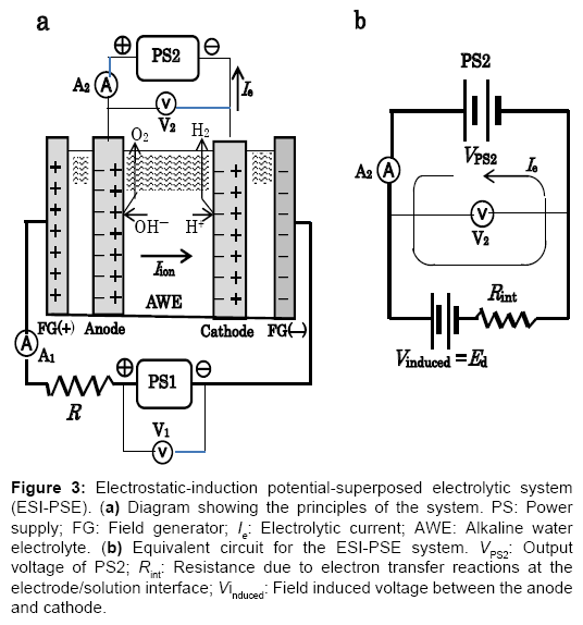
To take advantage of the internally self-sustaining electrostatic energy, the feature and essential part of the electrostatic-induction potential-superposed method are demonstrated as follows. The method termed ESI-PSE supplies potentials to the electrodes in a dual mode as shown in Figure 3a, i.e., the superposition of two voltages on the electrodes with two independent voltage sources; one is a biasvoltage source, which induces Ed at the cell electrodes and the other is a power supply, which provides power to the cell. Figure 3b is a closed circuit with two voltage sources connected in opposing directions. These sources can act in parallel independently, and supply the cell electrodes with individual potentials, which yields a superposition such that the resulting voltage between the cell electrodes equals the magnitude of the algebraic sum of the individual potential, i.e., Ed+ΔE. The performance of the cell can be explained by a series of steps. Firstly, when the PS2 output voltage VPS2=Ed, I=0 (null point) because of the usual condition of uniformity of the electrochemical potential throughout the electrolyte solution [7]. Secondly, if VPS2 is increased from the null point, then an electrolytic current I=Ie flows due to the total source voltage (emf) of ΔE =VPS2?Ed. Hence, the two sources can be replaced by a single source (PS2) that delivers ΔE. The bias-voltagesource does not need to produce electrical current, but only a static voltage because of the null-current condition at Ed. The cell voltage Ee, is the superposition ofΔE on Ed, and the entire corresponding electrolytic process is the superposition of the charge-transfer process where ΔE is applied, (i.e., where power is used) to the electrostatic process where Ed is applied, (i.e., where power is not used). If the current 2F flows to produce 1 mole of H2 and half a mole of O2, and the current efficiency is almost unity, as in a commercial electrolyzer, then the total power requirement reduces to the generalized form for any given cell, regardless of the decomposition voltage Ed, temperature, pressure, composition of electrolyte solution and cell dimensions:
P*=2FΔE. (4)
Figure 3: Electrostatic-induction potential-superposed electrolytic system (ESI-PSE). (a) Diagram showing the principles of the system. PS: Power supply; FG: Field generator; Ie: Electrolytic current; AWE: Alkaline water electrolyte. (b) Equivalent circuit for the ESI-PSE system. VPS2: Output voltage of PS2; Rint: Resistance due to electron transfer reactions at the electrode/solution interface; Vinduced: Field induced voltage between the anode and cathode.
Structure Of Electrolyzer
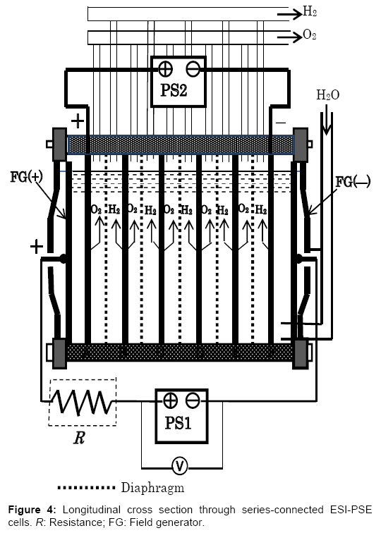
A single ESI-PSE cell generates a limited amount of H2 and O2. In practice, many cells are assembled into a stack, with the principles being the same. For example, the bipolar electrolyzer currently in use in industry offers considerable advantages, in that it may be used directly with the present cell structure as shown in Figure 4. This is a type of electrostatic-induction electrolyzer, but it remains a barrier potential type electrolyzer. The electrolyzer is typically operated with a single power supply PS1, which is responsible for the total power, i.e., the number of cells times the power per cell, I(Ed+ΔE). To change the power supply mode into the ESI-PSE scheme, it is sufficient to introduce minor modifications as follows. (1) The outermost pair of electrodes is used as a field generator and should be connected to the power supply PS1. (2) The power supply responsible for providing power should be connected to the electrodes next to the field generator electrodes. There is no need for lead wires to take current from each of the inner cells. The performance of this alternative electrolyzer may be determined by considering two steps that specify the electrical behaviors of the cells. (1) When the output voltage of power supply PS1 is VPS1=7Ed, the total field-generator voltage is divided among 7 channels in equal amounts of Ed. Thus, there is no current in the circuit involving PS1, and a voltage of 5Ed is induced between the electrodes A-F as a floating potential. The null-current condition means that PS1 does not need to provide current, but merely induce a static voltage. (2) If the power supply PS2 is connected to the electrode A-F with its polarity opposing the induced voltage, then the resultant electrolytic circuit is analogous to a closed circuit with two voltage sources that are in series and of opposing polarity. Next, if VPS2 is increased from 0 to 5(Ed+ ΔE), an electrolytic current Ie flows due to the emf of 5ΔE as a result of the potential superposition of 5ΔE on 5Ed. For an internal cell, the extra applied voltage over Ed is ΔE and the current flowing through is Ie; therefore, the power requirement per cell in this type of electrolyzer must be IeΔE. Thus, power requirement equivalency with a single ESI-PSE cell is established.
A resistor R is required between PS1 and field generator electrode, FG (+), such that the transitional current flowing through PS1 at Ed (Figure 2a) is lowered down to the level sufficiently low, as shown in Figure 2b. If the resistor R is not present, then PS1 causes extra power consumption. According to theoretical calculations, this power accounts for 40% of the power required when no transitional region is present and the electrolyzer runs at an extra applied voltage ΔE=0.2 V and a current density of J=1000 A/m2.
Energy Efficiencies
From the literature, the operating conditions for low temperature alkaline water electrolysis are: Temperature: 60-80°C; pressure: 1 atm; current density: 1000-3000 Am-2; cell voltage, Ee: 1.9-2.2 V; electrolyte: H2O-30% KOH. The factors that mainly affect the energy efficiency of the AFC are the utilization efficiency of fuels at the electrode reactions, the ΔG/ΔH ratio of the H2+1/2O2 →H2O oxidation reaction, and the voltage degradation factor, i.e., the voltage efficiency η= Ef / Ef° for the operating AFC, where Ef is the actual voltage of a cell undergoing oxidation and Ef° is the theoretical open-circuit voltage. The overall energy efficiency of a commercially available low temperature AFC is in the order of 60%. If the AFC is combined with the BAWE to form a closed single energy cycle, the energy efficiency of the developed energy cycle equals the energy efficiency of the AFC in the system for the reasons described below. The energy sources for the BAWE with ESIPSE electrodes in the system are the internally provided electrostatic energy plus the power returned from the AFC. The pure stoichiometric H2-O2 fuel completes the reaction, H2+1/2O2 → H2O, therefore, the utilization efficiency of the fuel may be deleted from the factors that affect the energy efficiency of the AFC. The oxidation bi-product, H2O, which contains the heat liberated by the exothermic reaction, is transferred to the BAWE and used for the endothermic reduction reaction. The thermodynamic factor, ΔG/ΔH, is thus also deleted, which leaves the voltage efficiency as the only factor, η= Ef /Ef°.
In this combined energy cycle, the main device is the fuel cell to produce electricity. The electrolyzer in this system is a backup reactor to synthesize fuel for the fuel cell. Part of the power generated by the fuel cell is returned to the electrolyzer, and the remainder represents the net power output. To represent the productive capacity, the cycle power efficiency is defined as the ratio ξ p of the net power extracted from the cycle, Pnet, to the power produced by the pure stoichiometric H2-O2 fuel, Pf:
ξp=Pnet / Pf (5)
If the voltage efficiency is taken into account, then for 1 mole H2,
Pf=2FηEf°. (6)
Mass balance in the cycle requires equality of the electrolytic and galvanic currents. If the current efficiency is assumed to be unity, then Equation (4) is subtracted from Equation (6) to yield the theoretical net power output of the cycle, Pnet . Hence, the cycle power efficiency is rearranged in the form:
ξp=Pnet / Pf=1-ΔE / ηEf°. (7)
Assessments have been made on the achievable cycle power efficiencies for the hydrogen redox power generation system when a commercially available AFC is combined with an existing BAWE that is connected to the ESI-PSE mode. Because ΔE=Ee—Ed, Equation (7) becomes:
Ee =ηEf °(1-ξp) + Ed. (8)
The energy efficiencies for the total generation system require the V-I characteristics for the BAWE and the voltage efficiency of the AFC. The V-I characteristics were determined using data for the operating conditions of typical electrolyzers, with j=1000, 3000 and 4500 A/m2 at Ee=1.9, 2.2 and 2.4 V, respectively, and also with reference to the literature [8,9]. Commercially available AFCs operate with a voltage efficiency of η=0.8 on average [10]. In view of Equation (8), points on the V-I curve are related to the corresponding cycle power efficiencies. Table 1 shows the achievable cycle power efficiencies and corresponding operational conditions required to BAWE and AFC. The energy efficiency for this energy cycle where the energy is created within the system is defined as follows. The purely stoichiometric H2-O2 fuel produced by the electrolyzer is the source of energy to convert into electricity so that the H2+1/2 O2→H2O oxidation reaction is performed in the fuel cell. The heat released is recycled for use in the endothermic reduction reaction at the electrolyzer, therefore, the standard free energy change for the oxidation reaction, |ΔG °|, is responsible for the electric power generation. On the other hand, the electrical energy delivered by the fuel cell is 2FηEd °. The energy efficiency is then given by the ratio of 2FηEd ° to |ΔG °|:
ξE=2FηEd °/ |ΔG °|=η. (9)
The power extracted from the generator is dependent on the rate of H2O-circulation inside the system. If the circulation rate is 1 mole H2O per second, then the power output is given by:
P=|ΔG °|ξE (kW). (10)
|ΔG °|= 232 kJ/mole H2O at 330 K and η=0.8 , therefore, if H2O circulates at a rate of 1 kg/s, then the net power output would be 1.03 × 10⁴ kW.
| Cycle power efficiency of hydrogen redox power generator | BAWE | AFC | |
|---|---|---|---|
| Single cell voltage | Current density | Voltage efficiency | |
| ξp (%) | Vcell (V) | J (Am-2) | η |
| 60 | 2.2 | 3000 | 0.8 |
| 70 | 2.1 | 2200 | 0.8 |
| 80 | 2.0 | 1400 | 0.8 |
Table 1: Operational conditions of BAWE and AFC for high cycle power efficiencies.
Suggested Generator
The proposed approach is to demonstrate that this electric power generation system may be realized with an energy cycle that consists of a fuel cell and a water electrolyzer with ESI-PSE electrodes as an energy supply scheme. This power generation concept assumes to use a low temperature AFC and a low temperature BAWE, both of which are commercially available: They are set side by side in parallel. The result of calculations using the commercial data for the operational conditions showed that the cycle power efficiencies ranging from 60 to 80% could be attainable, regardless of the total electrode surface area. Self-exciting capability of the HRPG system may be appreciated with respect to its cycle power efficiency. For example, if the HRPG using a nominal 100 kW fuel cell is operated with a cycle power efficiency of 70%, then it may be implied that the net power extracted from this HRPG is 70 kW.
Among all types of fuel cells, low temperature (ca, 25 to 70°C) AFC’s operate well at room temperature, yielding the highest voltages at comparable current densities. An AFC can be built from carbon materials and plastics that are anti-corrosive and low-cost. Therefore, this type of fuel cells is able to achieve a long operating life, approximately two years. The AFC is installed in a closed system; therefore, contamination of the alkaline electrolyte (H2O-KOH) by CO2 can be avoided. On the other hand, the BAWE also has the same advantages with respect to lifetime, construction materials and stability of the electrolyte. The same alkaline electrolyte is used for both devices, so that mutual contamination can be avoided. The preliminary system design is based on consideration of the mutual consistency for a stable operation of the total system. To maintain the mass balance in the system, the electrolyzer current must be controlled such that the rate of hydrogen consumption in the fuel cell equals the rate of hydrogen emission from the electrolyzer, if the current efficiency of the electrolyzer is unity. This system does not require the compressed hydrogen gas tank which is an explosion hazard.
Concluding Remarks
Toward achieving a breakthrough in the practical capabilities of high electric power generator that functions with both zero energy input, zero matter input and zero emissions, the basic concept of the hydrogen redox electric power generator (HRPG) have been developed. With this generation system, wide range of unique applications may be expected:
(1) Replacement of the thermal power generation with HRPG to reduce carbon dioxide emissions from coal and oil-fired electric power generation.
(2) The HRPG central-station power generation in the regions and countries where energy sources for power generation are unavailable.
(3) Hydrogen generator:
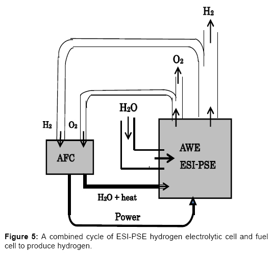
Figure 5 outlines the combined cycle of AWE electrolyzer with ESI-PSE and AFC to produce hydrogen. This system is of mutual consistency with the HRPG system shown in Figure 1, and is able to generate H2 without receiving electric power from outside of the cycle [1]. Part of the hydrogen generated by the ESI-PSE electrolyzer is returned to the fuel cell, and the remainder represents the net hydrogen output. In addition to cycling the generated hydrogen, H2O, which contains heat from the exothermic reaction in the fuel cell, is transferred to the electrolyzer for the use to its endothermic reaction. This system may achieve a highly positive hydrogen balance such that the hydrogen output of this cycle exceeds, for example, 70% of the hydrogen delivered by the ESI-PSE electrolyzer.
Because of the simplicity, effectiveness, cleanliness and selfexciting, this new generator HRPG, may offer a potential route for its practical application to an electricity-production system of the future.
References
- Ono K (2013) Fundamental Theories on a Combined Energy Cycle of Electrostatic Induction Hydrogen Electrolytic Cell and Fuel cell to Produce Fully Sustainable Hydrogen Energy, IEEJ Transactions on Fundamentals and Materials 133: 615-621.
- Ono K (2013) Energetically Self-Sustaining Electric Power Generation System Based on the Combined Cycle of Electrostatic Induction Hydrogen Electrolyzer and Fuel Cell, IEEJ Transactions on Fundamentals and Materials 135: 22-33.
- Ono K (2015) Theoretical Concept of Hydrogen Redox Electric Power Generation, IEEJ Transactions on Fundamentals and Materials 135: 456-466.
- Ono K (2015) Hydrogen redox electric power and Hydrogen energy generators, International Journal of Hydrogen Energy.
- Bard AJ, Faulkner LR (2001)Â Electrochemical metho d Fundamentals and Applications. John Wiley & Sons, Inc., USA, p: 139.
- Bard AJ, Faulkner LR (2001) Electrochemical method Fundamentals and Applications. John Wiley & Sons, Inc., USA, pp: 11-14.
- Christopher HA, Shipman CW (1968) Poisson Equation as a Condition of Equilibrium in Electrochemical Systems, J ElectrochemSoc., 115: 501-506.
- LeRoy RL, Janjua MB, Renaud R, Leuenberger U (1979) Analysis of time-variation effects in water electrolyzers, J ElectrochemSoc., 126: 1674-1682.
- Abe J (2008) Hydrogen Production by Water Electrolysis, Hydrogen Energy System 33: 19.
- Applby AJ, Foulkes FR (1989) Fuel Cell Handbook, Van Nostrand Reinhold, New York, pp: 295.
Citation: Ono K (2016) Concept of Hydrogen Redox Electric Power Generator. Innov Ener Res 5: 129.
Copyright: ©2016 Ono K. This is an open-access article distributed under the terms of the Creative Commons Attribution License, which permits unrestricted use, distribution, and reproduction in any medium, provided the original author and source are credited.
Select your language of interest to view the total content in your interested language
Share This Article
Recommended Journals
Open Access Journals
Article Usage
- Total views: 13766
- [From(publication date): 6-2016 - Jul 05, 2025]
- Breakdown by view type
- HTML page views: 12691
- PDF downloads: 1075

