Energy/Fuel Efficient and Enhanced Robust Systems Demonstrated with Developed Fractional Order PID Controller
Received: 18-Jan-2018 / Accepted Date: 27-Jan-2018 / Published Date: 31-Jan-2018 DOI: 10.4172/2576-1463.1000182
Abstract
In this brief article, the design and implementation of Fractional Order Proportional-Integral-Derivative (FOPID) controller is presented in analog and digital domains. Here we show the measured results for energy/fuel efficiency and enhanced robustness, as compared to classical PID controls. The FOPID controller is tested with DC-Motor, Magnetic Levitation System, and Brushless DC Motor, that we report in this article.
Keywords: Fractional calculus; PID; Fractional order PID; Fractional order Laplace variable; Pole-zero approximation; Iso-damping; Performance indices; Energy/fuel efficient control system
Introduction
Classical controls are in form of PID (Proportional Integral Derivative) controllers exist since 1910. The PID was invented in 1910 by Elmer Sperrys for ship auto pilot. However the ‘electronic’ circuit based conventional classical controllers such as PD, PI and PID have been applied in industry for over half-a-century to control linear and nonlinear systems. The tuning methods for PID controllers i.e. “Ziglers-Nichols” is well proven and exists since 1942.
Recently, such control schemes have been extended to their generalized form using fractional calculus (differentiation and integration of an arbitrary order). The FOPID controller has fractional order differ-integration operations [1-4]. In applications, where these non-integer order controllers (i.e. FOPID) are used there is added flexibility in adjusting the gain and phase characteristics as compared to integer order controllers as shown in Figure 1 [1,2]. The Figure 1a gives the transfer function (in frequency domain) of FOPID controller as 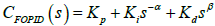 , with parameters α and β and the noninteger values (greater than zero). These parameters α,β ∈ R+, give two extra degrees of freedom in tuning as compared to three in number for the classical PID whose transfer function is CPID(s)= Kp+kis-1+Kds [1,2]. Note that classical PD, PI, and PID take only three points namely (0,1), (1,0) and (1,1) in the entire α - β plane, whereas the FOPID is having domain of operation in the entire first quadrant of α - β plane (Figure 1a). This flexibility makes fractional order control more versatile tool in designing robust and precise control systems. The fractional Laplace operators in the transfer function (i.e. s-α and sβ ) of FOPID corresponds to fractional integration of order α and fractional differentiation of order β, respectively [1,2]. Thus, in the time domain the controller output i.e. u(t) which is obtained via operation on real time error signal i.e. e(t) is
  . This has operation of fractional integration and fractional differentiation (Figure 1b). The operation Dtu x(t) is fractional derivative/integration with respect to variable t for a function x(t) , for fractional order u; u∈R [1-4]. When u=1, the operation is one-whole classical derivative, and with u= -1 the operation is classical one-whole order integration. This structure of FOPID controller is depicted in the Figure 1b. A better understanding of the potential of fractional calculus and the increasing number of studies related to the fractional order controllers led to the importance of studying aspects such as the analysis, design, implementation, tuning, and application of these controllers in diverse applications. Some of the results we briefly report in this article. For detailed study the readers may study the articles listed in references.

Figure 1: The concept of FOPID and structure of FOPID controller.
Algorithm For Practical Realization Of The Fractional Order Differentiators And Integrators For Analog And Digital Circuits
Fractional order differentiators and integrators are not available commercially. The fractional order Laplace element i.e. S±α when implemented into analog or digital circuits is called ‘fractance’ [5]. Implementation of these ‘fractance’ is by using a band-limited (ω1≤ ω ≤ ωh) integer order transfer function approximation. Thus, the fractional Laplace operator i.e. sα; α ∈R gets approximated by ratio of rational polynomials as 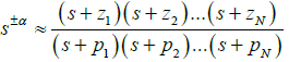 in the band ω1 ≤ ω ≤ ωh [1,2]. This rational approximation is then implemented by using analog circuit technique [6,7] and then using digital techniques [7-13].
A novel pole-zero interlaced approximation method (a new proprietary algorithm) is developed to approximate the fractional order Laplace operators [5,6]. The basic idea is of getting a constant phase is by slope cancellation of asymptotic phase plots for zeros and poles [1,2,5,6]. For fractional order integrator, first pole p1 is selected such that its asymptotic phase plot passes through point (ω1,ɸreq), then z1 i.e. the first zero gets selected; and thereafter subsequent poles and zeros are selected so as to keep the asymptotic plot constant at ɸreq= α(90°). For semi-integration operation α = -0.5 so we get ɸreq = -45°. Thus our objective is to have phase angle equal to ɸreq with an error less than or equal to eallowed , i.e. erms ≤ eallowed (Figure 2) for all frequencies ω such that ω1≤ ω ≤ ωh. For a n number pole zero-pair we have the essential formulas noted in the Figure 2, (tagged as Eqn). We note here the values of band limits i.e. ω1, ωh is based on system-identification, that is carried out a priori with the known dynamic model of the system [7,11-13].

Figure 2: Algorithm of pole-zero approximation method for realizing fractional Laplace operator as ratio of rational polynomials.
In the described recurring relation tagged as Eqn in Figure 2 we have a trim-parameter μ which is normally zero but is selected as to adjust density of pi , zi in the phase plot to have ɸavg as close to ɸreq. The details of its usage with several examples are in [5,6] and the range of μ is 0 ≤ μ < 2. The approximation with six-pole zero pair with ω =102 radian/sec , ωh =104 radian/sec with error ± 1° for α = -0.5 gives values of pi and zi (I = 1-6) is listed in Table 1, with plot depicted in Figure 3c.
| i | 1 | 2 | 3 | 4 | 5 | 6 |
|---|---|---|---|---|---|---|
| zi | -7.0795 | -51.286 | -371.54 | -2691.5 | -19,498 | -141,250 |
| pi | -2.6128 | -18.928 | -137.12 | -993.34 | -7191.6 | -52,131 |
Table 1: The pole and zero of the rational approximation of semi-integration on band limited range of 100-10,000 radian/sec.

Figure 3: Analog realization of band limited fractional differ-integral operator.
The rational approximation of semi-integration operation is thus following (from Table 1)

For a fractional order differentiator in the band limit of ω1≤ ω ≤ ωh we do first selection of first zero z1 and then first pole p1; and rest is same recurring method that is described for fractional integrator. Therefore for semi-differentiator i.e. s0.5 the approximation will be reciprocal of what we obtained for semi-integration i.e. s-0.5 as above.
The algorithm gives the rational approximation in form of band limited transfer function for the fractional Laplace variable s±α as indicated above. The digitization is done from s to z domain by using Tustin formula (Figure 2), i.e.  . With Ts = 0.0001sec [7] we obtain digitized representation of semi-integration (Table 1) as following transfer function.

The discrete transfer function is implemented by using standard digital-filter algorithm [7,11-13]. With the obtained approximated fractional Laplace operator for sα, sβ the FOPID transfer function i.e. 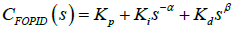 is dicretized to z domain (Figure 1). Thereafter choosing the standard digital-filter formula a difference equation for discretized CFOPID (s) is obtained. This difference equation relates discretized e(t) stated as ek to get discretized controller output u(t) stated as uk which is given as
  [7,11-13].
Analog FOPID Controller
The fractional order impedance or ‘fractance’ circuit is realized with two port network having passive components resistor (R) and capacitor (C) [5,6], along with operational amplifiers (Figure 3a).This analog circuit of Figure 3a is designed to generate the pole-zero pairs by use of available R - C components designed for a given fractional order (α; α ∈R). The asymptotic phase plot of fractional order integrator is shown in Figure 3c for α= -0.5; for frequency band of 102 ≤ ω ≤ 104. The Figure 3b shows a photograph of developed ‘fractance’ circuit with six poles-zero pair i.e. having six circuits i=1-6 of Figure 3a connected in series with different values of Ri , Rf , Ci ; Rf’. Refer Table 2 for the values of the six circuits [6].
| Circuit Section i | 1 | 2 | 3 | 4 | 5 | 6 |
|---|---|---|---|---|---|---|
| Ci | 1µF | 1µF | 0.47 µF | 0.068 µF | 10nF | 2.2nF |
| Ri’ Rf’ | 382.7kΩ | 52.8kΩ | 15.52kΩ | 14.8kΩ | 13.8kΩ | 8.71kΩ |
| Ri Rf | 223.9kΩ | 30.9kΩ | 9.08kΩ | 8.66kΩ | 8.13kΩ | 5.1kΩ |
Table 2: R-C values of six circuits for realizing the half order integrator.
A semi-integrator for the required specifications of band-limited approximation is realized by six poles-zero pairs as per algorithm of Figure 2, presented in Table 1. The resistors and capacitor values of the circuit of Figure 2a given in Table 2 is by formula [6].
for fractional Integrator 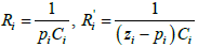
for fractional differentiator 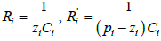
In the formula we select first the available value of capacitor and then the resistor value is calculated. The exact resistor value is adjusted by using standard E48 series resistors with a potentiometer in series. The algorithm, as shown in Figure 2, is developed to determine the actual values of resistor and capacitor components. Then these ‘fractance’ circuits are organized (with operational amplifiers) as shown in Figure 1b, to get analog FOPID controller. The analog FOPID controller is shown in Figure 4a, it has got facility to select fractional order of differentiation β, and fractional order integrator α as 0.2 , 0.5 and 0.8; and also via potentiometer one can select the gain values of the ‘gains’ Kp, Ki and Kd.

Figure 4: Analog FOPID controlling Speed of DC motor emulator.
To verify the analog FOPID controller performance, a hardwired emulator circuit of DC motor (i.e. plant) is developed. Plant consists of a DC motor and a load with specification as: Speed N=2000 rpm , the armature resistance as Ra= 2Ω , armature inductance as La=3mH , rotor inertia J= 1.78× 10⁻⁴ Kg- m2 , motor constant Kv=1.02, DC armature voltage Va =24V [6].The plant transfer function G (s) of DC motor a second order stable function realized by circuit is 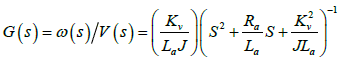 . The complete hardware setup is shown in Figure 4a. Performance test result of DC motor model emulator circuit is shown in Figure 4b.The performance of the realized analog FOPID controller is tested with the DC motor emulator. The FOPID performance indicates that the controller with α,β= 0.5 could make it possible to maintain the desired control on the output speed. The response of DC motor model with FOPID controller is shown in Figure 4c.
Enhanced Robustness-‘iso-damping’ Observed
The variation in gain from 40 to 100 is set with PID and FOPID controller. The recorded response is given in the CRO traces of Figures 5 and 6. From CRO traces of Figures 5a, 5b it is observed that the peak overshoot with a PID controller is varying widely, when the gain is changed from 40 to 100. Whereas, from CRO traces of Figures 6a, 6b the peak overshoot is almost constant in FOPID controlled system, while the gain is changed from 40 to 100. This phenomena of overshoot remaining constant over wide parametric spread is called ‘iso-damping’, is a feature what we get via using FOPID; thus we have enhanced robustness in controls [1,2,6]. The comparison of overshoot variation is also tabulated in Table 3 [6].
| Values of Kp (gain) | Close-loop PID | Close-loop FO-PID | ||
|---|---|---|---|---|
| % Peak overshoot simulation results | % Peak overshoot hardware results | % Peak overshoot simulation results | % Peak overshoot hardware results | |
| 40 | 22 | 30 | 25 | 24 |
| 50 | 30 | 36 | 25 | 24 |
| 60 | 45 | 44 | 25 | 24 |
| 70 | 53 | 52 | 25.5 | 25 |
| 100 | 65 | 60 | 25.5 | 25 |
Table 3: Comparison of peak overshoots with variation of gain for PID and FOPID.

Figure 5: Hardware results of PID with DC motor emulator at different parametric gain variation.

Figure 6: Hardware results of FO-PID with DC motor emulator at different parametric gain variation.
The Table 3 show that with variation in gain from 40-100 the closed loop response is having overshoot constant at about 25%. This is ‘isodamping’, that is got by FOPID while the overshoot varies from 22- 65% in case of PID. This is enhancement in robustness experimentally demonstrated by use of FOPID.
Digital FOPID Controller
Magnetic levitation system controlled by PID and FOPID controller
This designed digital FOPID controller is used to control highly non-linear and inherently unstable Magnetic Levitation System (Mag- Lev) in hardware-in-loop mode as shown in Figure 7a. Mag-Lev is basically an electromagnetic system which levitates ferromagnetic objects in space by the magnetic force induced due to the electric current flowing through the coils around a solenoid [7]. The tuned controllers that are compared are having transfer functions, for PD as CPD(s) = 4 +2s , PID as CPID (s) = 5.5 +0.2s-1 + 2s and FOPID as CFOPID (s)= 7+12s-0.8+s0.4. The continuous time pole-zero interlaced approximation method (Figure 2) to get rational approximation for s±α is discretized, using Tustin digital formula (with Ts =0.01 Sec) converting s- domain to z- domain, with sampling time Ts = 0.01 sec; in the band102 ≤ ω ≤ 104 and then a digital FOPID controller is developed [7].

Figure 7: Controlling Mag-Lev system by PD, PID and FOPID.
The performance analysis for digital classical PID, PD, and FOPID is carried out. The results in CRO traces of Figures 7b, 7c, 7d that show a better control over position accuracy with lesser control efforts u(t) is achieved with FOPID over the conventional methods i.e. PID, PD [7]. In practical terms, this improvement of controlling with lesser effort translates to better energy/fuel efficiency [1,2,7-9].
The control signals u(t) along with measures as Performance Indices (P.I) those are Integral Absolute (IA), Integral Time Absolute (ITA), and Integral Square (IS) [10] are the indicator of energy utilized by the controller, an important factor in the industrial control paradigm. In this context, the fractional order controller proves to be superior to the classical controller. The comparison is presented between PD, PID, and FOPID controls in Figure 8, as for ball position error (Figure 8a) and controller performances (Figure 8b) via comparing performance indices IA, ITA, and IS, calculated on
(i) Error signal e(t) and
(ii) Control signal u(t) i.e. output of the controller.

Figure 8: Comparison of controls PD, PID, and FOPID in Mag-Lev system.
DC motor speed control by PID and FOPID controller
The digital FOPID controller is tested for 1.5kW industrial DC motor drive [11,12]. Speed control scheme of buck converter fed DC motor drive is shown in Figure 9a. Here, a reference speed is given as set point for FOPID controller, which provides the control signal computing the error generated in the control scheme. The PWM pulses are generated at frequency of 25 KHz with corresponding duty-ratio proportional to the controller output [11,12]. This signal operates the switch of buck converter and regulates the armature voltage of the DC motor. The controller is implemented on Digital Signal Processor (DSP) TMS320F28027 and TMS320F28377s. An industrial DC motor drive is developed as shown in the Figure 9b.

Figure 9: DC motor speed control by FOPID.
Here, it is recorded that tuned PID used for this DC motor is CPID (s) =115.6 +0.22 s-1+1.6s and tuned FOPID used is CFOPID (s) =15.2 + 0.04 s-1.4 + 2.4s1.2 . This tuning resulted in minimizing the Performance Indices (P.I) as shown in the Table 4, with respect to error signal e(t). The Table 5 gives the values of performance indices of controller effort with respect to control signal of the controller i.e. u (t). The measurement is done for armature current and armature voltage for various speed settings for DC motor, in no-load condition and with loaded condition (coupled to a generator and then loading the generator via resistive load banks). The Figure 10 displays the experimental result.
| S.No. | Controller | ITAE | IAE | ISE |
|---|---|---|---|---|
| 1 | PID | 34.21 | 46.75 | 7454 |
| 2 | FOPID | 14.94 | 20.85 | 6086 |
Table 4: Minimized performance index for error signal for PID & FOPID controller.
| S.No. | Controller | ITACE | IACE | ISCE |
|---|---|---|---|---|
| 1 | PID | 46.56 | 51.35 | 10080 |
| 2 | FOPID | 20.85 | 50.63 | 6663 |
Table 5: Minimized performance index for control effort for PID & FOPID controller.

Figure 10: Measured power input to DC motor for control with tuned PID and tuned FOPID, shows averagely 21%less power is drawn when controller is FOPID
It is observed that averagely 21.3% less power is drawn from DC source at no-load condition and averagely 19.6% less power is drawn at loaded condition for speed settings from 500RPM to 1300RPM. This is direct evidence of having Energy/Fuel Efficiency by using FOPID.
BLDC motor speed control by PID and FOPID controller
The speed control scheme for FOPID controller fed brushless DC motor (BLDC) 0.5kW, 350 RPM [13] drive is shown in Figure 11a. Here, the scheme is having FPGA-in-the-loop. The digital FOPID controller is implemented on Altera FPGA DE2-115 board [13]. Figures 11b-11d gives the comparison between the tuned PID controller and tuned FOPID controller. The Figure 12 show the comparison of control signal and phase current of BLDC motor controlled by PID & FOPID. We observe significant reduction in the RMS phase current drawn while controlling via FOPID controller as compared with classical PID controller.

Figure 11: BLDC Motor control by PID/FOPID.

Figure 12: Performance comparison of BLDC motor speed control with PID and FOPID.
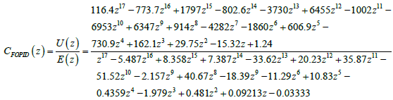
The tuned FOPID transfer function is CFOPID(s) = 4.25+ 0.2s-1.21+ 0.009s0.6 [13]. The fractional Laplace variables s-1.21 and s0.6 we approximate as per algorithm described in the form 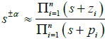 in the frequency band10-1 ≤ ω ≤ 103 with phase angle error eallowed= 1° (Figure-2) Then the obtained expression for CFOPID(s) we discretize by Tustin method [13] with Ts=0.001sec to get FOPID in z - domain as following
Fractional Calculus Engineering Laboratory
All these experiments are kept in Fractional Calculus Engineering Laboratory a first of its kind [14]. This laboratory provides a platform to develop Fractional Order Control Systems for industry and academic institutes. This laboratory is in use since November, 2016; at Dept. of EE, VNIT-Nagpur.
Conclusions
These practical demonstrations of implementation of fractional calculus in control science, gives a first of its kind a laboratory called ‘Fractional Calculus Engineering Laboratory’; where our aim is to have more fractional calculus based controllers and advanced methods developed for industrial usage. Though there is no commercial manufacturer or R&D institute using fractional calculus in controls, yet in future we hope this platform will be used for such developments for especially energy efficient and enhanced robust systems. Presently our aim is to make few more systems on power electronics of electro mechanical drive and energy conversion systems using fractional calculus; and take this laboratory to industry houses and academic institutes & universities. However, it is satisfying to see the long standing conjecture/hypothesis of fuel/energy efficient controls is realized via using fractional calculus. Still we have miles to go.
Acknowledgment
The work supported by the Board of Research in Nuclear sciences of the Department of Atomic Energy, India. Sanction No. 2007/36/81-BRNS/2907 and Sanction no. 2012/36/69-BRNS/2951. Authors acknowledge the efforts of Prof Ashiwin Dhabale, Amit Chopade, Rutuja Dive and Ruchi Jain of VNIT.
References
- Das S (2007) Functional Fractional Calculus for System Identification & Controls, Springer-Verlag.
- Oldham KB, Spanier J (1974) The Fractional Calculus, Academic Press, New York.
- Miller KS, Ross B (1993) An Introduction to The Fractional Integrals and Derivatives-Theory and Applications, Wiley, New York.
- Dhabale AS, Dive R, Aware MV, Das S (2016) A new method for getting rational approximation for fractional order differ-integrals. Asian J Controls 18: 1-10.
- Aware MV, Jughare AS, Khubalkar SW, Dhabale A, Das S, et al. (2017) Design of new practical phase shaping circuit using optimal pole-zero interlacing algorithm for fractional order PID controller, Springer’s Analog Integrated Circuit Signal Processing. 91: 131-145.
- Chopade AS, Khubalkar SW, Junghare AS, Aware AV, Das S (2016) Design and implementation of fractional order PID controller using optimal pole-zero approximation method for magnetic levitation system. IEEE/CAA J Automatica Sincaol pp 1-12.
- Das S, Biswas BB (2005) Fuel efficient nuclear reactor controls. Int Conf on Nuclear Engineering, ICONE-13 (50843) Beijing.
- Das S, Biswas BB (2007) Controlling Nuclear Plants with Fuel Efficiency. International Journal of Nuclear Power atw-Gmbh 2: 107-116.
- Nagrath IJ, Gopal M. Control Systems Engineering (Second Edition), Wiley Eastern Limited New Age International Limited.
- Khubalkar SW, Chopade AS, Junghare AS, Aware MV, Das S (2016) Design and Realization of Stand-alone Digital Fractional Order PID Controller for Buck-Converter fed DC Motor, Circuits, Systems & Signal Processing. 35: 2189-2211.
- Khubalkar SW, Junghare AS, Aware MV, Chopade AS, Das S (2017) Demonstrative Fractional Order - PID Controller based DC Motor Drive on Digital Platform, ISA Transactions.
- Khubalkar SW, Junghare AJ, Aware MV, Das S (2017) Modeling and control of permanent-magnet brushless DC motor drive using fractional order proportional-integral-derivative (FOPID) controller. Turkish J Electrical Engineering & Computer Sciences pp 4224-4242.
- https://timesofindia.indiatimes.com/city/nagpur/VNIT-develops-energy-minimizing-controller-transfers-tech-to-BARC/articleshow/55444793.cms
Citation: Das S, Aware MV, Junghare AS, Khubalkar SW (2018) Energy/Fuel Efficient and Enhanced Robust Systems Demonstrated with Developed Fractional Order PID Controller. Innov Ener Res 7: 182. DOI: 10.4172/2576-1463.1000182
Copyright: © 2018 Das S, et al. This is an open-access article distributed under the terms of the Creative Commons Attribution License, which permits unrestricted use, distribution, and reproduction in any medium, provided the original author and source are credited.
Select your language of interest to view the total content in your interested language
Share This Article
Recommended Journals
Open Access Journals
Article Tools
Article Usage
- Total views: 5146
- [From(publication date): 0-2018 - Dec 19, 2025]
- Breakdown by view type
- HTML page views: 4198
- PDF downloads: 948