Set-up Errors and Imaging Verification Protocols for Head and Neck Cancers Radiotherapy in Morocco
Received: 21-Jan-2019 / Accepted Date: 28-Jan-2019 / Published Date: 04-Feb-2019
Abstract
Purpose: The goal of this study, the first of its kind in Morocco, was to evaluate 3D set-up errors and to propose optimal margins for (Planning Target Volume) coverage in head and neck cancers. We investigated if others imaging frequency protocols were as effective as the daily one.
Methods: The alignment data from 20 patients, with daily orthogonal kilovoltage images, were collected and analyzed. The population systematic and random errors and the 3D vector of displacements were calculated. The (Clinical Target Volume) to PTV margin was generated with mathematic formulas (van Herk, Stroom, and ICRU). Other imaging protocols were simulated to evaluate the effect of imaging frequencies on the set-up errors: daily, No Action Level 5, extended No Action Level, weekly.
Results: Ninety eight percent of the set-up deviations were within 5 mm in all three directions. The population systematic and random error ranged from 0 to 0.35 mm and from 4.6 to 5.6 mm respectively. The CTV-PTV margin was, using van Hersk formulae, 4.23, 4.23, 3.96 mm in AP (Top), ML (Center) and SI (Bottom) directions respectively. There was no difference between the daily protocol and eNAL protocol (p=0.08) with 98% and 96.4% of 3D vectors within 3D vector PTV respectively. The eNAL protocol provided the best coverage of residual set up errors by the calculated CTV to PTV margin especially in the AP direction (95.8% with p<0.001).
Conclusion: A 5 mm extension of CTV to PTV margin seems to be the optimal margin. The eNAL could be strongly considered as a verification imaging protocol; however more studies are needed to confirm this result.
Keywords: Set up errors; PTV margin; Verification imaging protocol
Introduction
The main goal of Radiotherapy (RT) planning is to deliver the prescribed dose to the target tissues while limiting the dose to nearby healthy organs “risk organs”, in order to increase the control of tumor growth and to minimize side effects [1]. RT of head and neck cancers HNC is a great challenge [2], because of the shape complexity and the proximity of the target and risk tissues.
Therefore, the evaluation of RT related errors or uncertainties, even undesirable, are an unavoidable step of the RT process. They are defined as the difference between the actual and intended position with respect to radiation delivery. Each set-up error consists of a systematic component, as well as a random component [3].
The coverage of target volume depends on the consideration of setup errors in RT process, to prevent inadvertent irradiation of adjacent normal tissues or partial missing of target volumes. Planning target volume PTV that encompasses the clinical target volume CTV with some margins to account for such uncertainties in patient positioning, organ motion, and beam geometry is universally accepted today as the benchmark for RT dose prescription [4,5].
The measurement of set-up errors by portal imaging or on board imaging OBI system with kilovoltage Kv images is an accepted practice [6]. The radiation oncology community has performed such assessments in order to reduce PTV margins, particularly for highprecision radiotherapy [7]. It is recommended that every institution generate data on its set-up accuracy because of the experience of RT staff can have a great impact on daily positioning of patients [8].
Daily imaging verification protocol seems to be recommended especially for patients treated with intensity modulated radiotherapy (Intensity Modulated Radiation Therapy) as all setup deviations are corrected before treatment; however image acquisition over the entire treatment course is resource intense [9]. Thus, the evaluation of other imaging frequencies, as effective as the daily imaging protocol, is a subject of research.
Our study focused on the inter-fraction patient set-up uncertainties analysis using daily image guidance for patients treated for HNC with volumetric modulated arc therapy technique VMAT. The goal was to evaluate three-dimensional 3D set-up errors and to propose adequat margins for PTV coverage in head and neck RT. Also we investigated if other imaging frequency protocols were as effective as the daily imaging protocol.
Methods
Patient group
The alignment data from 20 patients treated for head and neck cancers (nasopharynx, larynx, oral cavity, maxillary sinus and nasal fossa cancers) with RapidArc® (the Varian solution of VMAT), with daily orthogonal kv planar images, were collected and analyzed. Fifteen of these patients were treated for nasopharyngeal cancer, 3 for oral cavity cancer, for maxillary sinus cancer and for nasal fossa cancer.
Informed verbal consent was obtained from all patients. This study was submitted to and approved by research and ethics committee of military teaching hospital Mohamed V.
Image-guided radiation therapy system: Treatment set-up and verification
Patients were immobilized in supine position using 5-point customized thermoplastic masks (CIVCO®) (Figure 1). Computed Tomography CT imaging for treatment planning was performed with General Electric CT using a slice thickness of 2.5 mm. After delineation of CTVs by the radiation oncologist, a 5mm margin (3mm if critical structures) was applied around CTVs to generate PTVs.

Figure 1: Five-point customized thermoplastic masks (CIVCO®) used for immobilization of patients treated for HNC with VMAT.
After approbation of treatment plan by the radiation oncologist, a digitally reconstructed radiograph DRR of the beam’s eye view BEV were generated and registered in the treatment planning system TPS and were considered to be the reference images.
All patients were treated on a Clinac 2300 iX (Varian Medical Systems, Palo Alto, CA) with On Board Imaging OBI (version .4) capabilities. Daily basis verification was performed to ensure the accuracy of the OBI system calibration.
Before each fraction of RT course, 2 orthogonal Kv images were generated with OBI device; anterior-posterior AP and lateral images (right or left). The comparison between Kv images and DRRs was performed by means of anatomy matching software Portal Vision Advanced Imaging (Varian Medical System); we realized an automatic bone matching which is controlled manually based on bone anatomy landmarks, previously defined.
In order to avoid inter-observer variation, one radiation therapy technologist performed all the measurements. The mismatch found in any of the three directions; AP (dorso-ventral direction), medial-lateral ML (left-right direction) and superior-inferior SI (caudo-cranial direction), were applied by couch shifts and recorded before treatment delivery.
For the purpose of documentation and analysis anterior, superior, and right sided shifts were coded as positive shifts and posterior, inferior, and left-sided shifts as negative shifts. It was assumed that the routine periodic quality assurance employed for the linear accelerator would ensure minimal impact of the potential sources of errors such as laser alignment, display accuracy, isocentric accuracy..
Data Analysis
Systematic and random errors
For 20 patients, set-up deviations in the three directions (AP, ML and SI) were collected and analyzed. Rotational errors were not assessed in this study. Displacements or shifts were assessed offline with Varian Offline Review anatomy matching software by 2 radiation oncologists. The mean displacements or deviations, population systematic (Σsetup) and random errors (σset-up), and the 3D vector of displacements were calculated.
A patient set-up deviation (μ) is the difference between the position of the part of the patient’s body irradiated at treatment and the intended position. This set-up deviation consists of two components; random and systematic components. The systematic component, refers to the“treatment preparation errors”, is defined as the same deviation in the same direction for each fraction throughout the whole course of treatment, whereas the random component, varying from day-to-day “treatment execution errors” [3].
For each patient, systematic and random deviations were calculated for the three directions (AP, ML and SI) separately.
The individual systematic set-up deviation for a patient p (mp) refers to the mean deviation of np images. (eqn. (1)) [1].
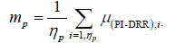 (1)
(1)
The individual random set-up deviation (σr and;p) refers to the standard deviation of the distribution of μ deviations around mp for a patient p in a given direction (eqn. (2)) [1].
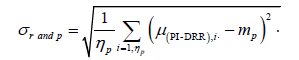 (2)
(2)
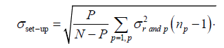 (3)
(3)
The population random error (σset-up) which is the random set-up error for all the P patients in a given direction refers to the standard deviation of the σrand,p distribution (eqn. (3))[1].
The population systematic error (Σset-up) which is the systematic set-up error for all the P patients in a given direction refers to the standard deviation for the mp distribution (eqn. (4)) [1].
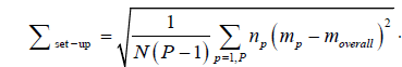
Where the overall mean systematic error for all the P patients (moverall) in the study, with N is the total number of images is given by eqn. (5) [1].
 (5)
(5)
The accuracy of the following statistical approach depends on the total number of patients P and images N used in the study [1]. We consider that both random and systematic components are normally distributed, in order to perform this calculation method [3].
CTV to PTV margins
The CTV-PTV margin can be calculated with several mathematic formulae. The ICRU 62 [5] proposes to add systematic and random errors in quadrature. Others formulas use coverage probability matrices and dose population histograms; Stroom’s margin [10] recipe (2Σ +0.7σ) ensures that, on average, 99% of the CTV receives more than or equal to 95% of the prescribed dose. The formula by van Herk et al. [11] (2.5Σ+0.7σ) ensures that 90% of patients in the population receive a minimum cumulative CTV dose of at least 95% of the prescribed dose.
3D vectors
For each fraction, the 3D vector length was calculated by combining quadratically the measured D deviation in the three directions and then the mean 3D vector (for all fractions) was also calculated.
Different Imaging Frequency Protocols
Directional deviations over the entire 64 fractions were considered as ‘true set-up errors’ and three-dimensional transitional deviation (3D vector) were calculated for all fractions. Other imaging protocols were simulated for a comparison to evaluate the effect of imaging frequencies on the set-up errors:
A) Protocol I (daily): Data collected fromdaily treatments “true setup errors”.
B) Protocol II (No Action Level protocol “NAL5”): Images were obtained for the first 5 consecutive fractions of a course of treatment. Average shifts were calculated from the first 5 days of imaging and subtracted from subsequent fractions “residual set up errors”. The 3D vector for each fraction was calculated from these residual set up errors.
C) Protocol III (extended No Action Level protocol “eNAL”): During the first three treatment fractions, patients were imaged. From the fourth fraction, a setup correction was applied for the mean setup error derived from the previous fractions. Measurements were repeated weekly, and the correction vector was updated by use of a linear fit through all measured displacements. The 3D vector for each fraction was calculated from these residual set up errors.
D) Protocol IV (weekly): Shifts were derived from the images performed weekly (one image’s verification per week). Based on these image’s verifications, deviation’s correction was performed, if necessary, and applied to the four subsequent fractions for that week.
Then the 3D vector for each fraction was calculated from these residual set up errors.
The 3D vector was calculated as the square root of the value of the summation from the square of each simulated directional shift (residual set up errors).
The comparison between protocols was based on:
• The proportion of residual set-up errors within the calculated CTV-PTV margin using van Herk formulae in the three directions.
• The proportion of 3D vectors within the 3D vector calculated from the CTV-PTV margin using van Herk formula “3D vector PTV”.
Statistical Analysis
The Kolmogorov-Smirnov test was used to evaluate the variable distribution. The khi2 test was used for comparison between qualitative variables. Statistical Package for Social Sciences (SPSS version 20) and Microsoft Office Excel (MS Office 200) were used statistical analysis.
Results
Directional shifts were measured in 614 fractions, with an average of 61.4 Kv images per patient, in the three directions; AP, ML and SI with a Gaussian distribution (Figure 2). The mean displacement in AP; ML; and SI direction was -0.3 mm (range -6 to +9 mm); -0.8 mm (range -9 to +7 mm); and 0.1 mm (range -5 to +7 mm) respectively. Ninety eight percent of the set-up deviations were within 5 mm in all three directions (Table 1).

Figure 2: Histogram of directional shifts in all three directions (a: AP, b: ML and c: SI).
| All directions | AP direction | ML direction | SI direction | |
|---|---|---|---|---|
| Set-up deviations ≤5mm | 98% | 97.90% | 97.70% | 99.20% |
Table 1: Proportion of set-up deviations within 5 mm in the three directions.
Systematic and random errors
The population systematic error (Σset-up) in AP; ML; and SI direction was 0., 0.35 and 0.27 mm respectively. The population random error (σset-up) in the same directions was 5.6, 4.8 and 4.6 mm respectively (Table 2). The median 3D vector of displacements was 2.45 [2; 4] mm.
| AP | ML | SI | Average | |
|---|---|---|---|---|
| Min (mm) | -8 | -9 | -5 | -7.3 |
| Max (mm) | 9 | 7 | 7 | 7.6 |
| Moverall (mm) | 0.56 | 0.46 | 0.1 | 0.37 |
| ∑set_up (mm) | 0.1 | 0.35 | 0.27 | 0.24 |
| σset_up (mm) | 5.6 | 4.8 | 4.6 | 5 |
Table 2: The summary of results for the population systematic (∑set-up) and random (σset-up) errors AP, ML and SI directions.
Margin calculation
The CTV-PTV margins were calculated using the International Commission on Radiation Units and Measurements (ICRU) Report 62, Stroom’s, and van Herk’s formulas (Table 3).
| ICRU 62 | Stroom | Van Hersk | |
|---|---|---|---|
| AP (mm) | 5.69 | 4.18 | 4.23 |
| ML (mm) | 4.86 | 4.11 | 4.23 |
| SI (mm) | 4.66 | 3.82 | 3.96 |
Table 3: CTV to PTV margins according ICRU 62, Stroom’s and van Hersk’s formulas.
Comparison between Imaging Frequency Protocols
There was no difference between the daily protocol and eNAL protocol (p=0.08) with 98% and 96.4% of 3D vectors within 3D vector PTV respectively (Table 4). The eNAL protocol provided the best coverage of residual set up errors within the CTV-PTV margin calculated by van Hersk formula especially in the AP direction (95.8% with p<0.001) (Table 5).
Imaging frequency protocols |
3D vector ≤7,17mm | p value (khi2 test) |
|---|---|---|
| Daily | 98% | - |
| NAL5 | 94,3% | 0.001 |
| eNAL | 96,4% | 0.081 |
| Weekly | 95,2% | 0.006 |
Table 4: Comparison between proportions of 3D vector within 3D vector PTV according to imaging frequency protocols.
| NAL5 | eNAL | Weekly | p value (khi2 test) | |
|---|---|---|---|---|
| AP (≤ 4,23) | 90,1% | 95,8% | 93,6% | <0,001 |
| ML (≤ 4,23) | 94,5% | 95,1% | 92,8% | 0,213 |
| SI (≤ 3,96) | 91,7% | 94,1% | 90,9% | 0,085 |
Table 5: proportion of residual set up errors within CTV-PTV margin depending on imaging frequency protocols.
Discussion
This study, the first of its kind in Morocco, analysed the setup accuracy, using the concept of systematic and random errors, of patients treated for HNC with daily imaging set-up verification, in order to generate the optimal CTV to PTV margins. Ninety eight percent of the set-up deviations were within 5 mm. Also The CTVPTV margins, according to van Hersk formula, were within 5 mm in all three directions.
We also compared virtually different imaging frequency protocols with the daily protocol and we found that the eNAL protocol seems to be an attractive option as it allowed the best coverage of residual set-up errors (94% to 95.8%).
It is very important to assess and reduce patient set-up errors, especially with IMRT or VMAT, because the sharpness of the gradients in the treatment plan makes the impact of set-up errors on delivery treatment accuracy more important; Xing et al. [12] observed that a 3-mm deviation in the couch position in the AP direction resulted in a 38% decrease of the minimal target dose or in a 4% increase of the minimal spinal cord dose. Increasing the number of beams in an IMRT treatment plan will increase the sharpness of the gradients around OARs and consequently the sensitivity to set-up errors increase [13].
In the published studies [1,8,14-20], the population systematic errors varied between 0.02-3.2 mm versus 0.24 mm in this study which can reflect a rigorous “treatment preparation”. In the other side, the population random errors were larger (5mm versus 0.4-2.9 mm). Thus, it was clear that set-up errors were attributed to random component, in other words, to “treatment execution”, which can be hopefully improved and reduced with training and practice experience.
There are several formulas to generate the optimal CTV to PTV margin; The ICRU 62 [5] supposes that random and systematic errors have the same contribution to the dose distribution, which is uncertain. Random errors blur the dose distribution whereas systematic errors are responsible of a dose distribution shift [21]. Others formulas use coverage probability matrices and dose population histograms; Stroom’s margin [10] recipe ensures that, on average, 99% of the CTV receives more than or equal to 95% of the prescribed dose. The formula by van Herk et al. [11] ensures that 90% of patients in the population receive a minimum cumulative CTV dose of at least 95% of the prescribed dose and it seems to be the most appropriate [8]. In this study, the CTV to PTV margins using van Herk’s formula were 4.23, 4.23, and 3.96 mm in AP; ML; and SI direction respectively( <5mm). Using this formula, Strbac et al. [1] concluded that a 6-mm extension of CTV to PTV margin, as the lower limit, is enough. Gupta et al. [8] found, in 25 patients irradiated for head and neck cancers, that the CTV to PTV margins was 3.76, 3.83 and 4.74 mm in AP, ML and SI direction respectively. Suzuki et al. [20], in 22 patients with head and neck or brain cancers who were irradiated with IMRT, adopted a PTVmargin of 5 mm.
There are many others publications assessing set-up margins in HNC [14-19]. However, caution should be exercised while comparing data from different series as each group has used different model parameters to derive cumulative set-up errors. Different margin generating recipes lead to a different probability of target volume coverage in different population setting depending on the distribution of shifts. It is therefore suggested that before adopting any published margin recipe, factors that can potentially impact upon margins should also be taken into consideration [8].
There are a few limitations in this study; firstly, the orthogonal Kv images do not take into account potential rotational shifts. Secondly, based on bony landmarks, Kv images do not give information about organ motion. According to ICRU Report 62 [5], the uncertainties related to organ shape and position should be considered by taking a margin around the CTV to generate an Internal Target Volume ITV. A second margin, referred to set-up errors, around ITV should be applied to obtain PTV. Suzuki et al. [20] analysed the intra-fractional organ motions during IMRT for head and neck tumors and reported that systematic and random set-up errors for organ motion ranged from 0.2 to 0.8 mm and 0.3-0.6 mm, respectively. Taking into account this margin, a 5 mm extension of CTV to PTV margin seems to be reasonable in our institution as ninety eight percent of the set-up deviations were within 5 mm in all three directions.
Thirdly, a potential bias in the interpretation of the set-up errors related to the observer’s appreciation during image registration. Van Lin et al. [22] reported that the difference between two observers’ averaged overall patients is 0.1 mm or less for all directions.
Daily online verification protocol seems to be the adequate frequency, especially for patients treated with IMRT as all setup deviations are corrected before treatment. However image acquisition throughout the whole course of treatment is sometimes difficult to ensure and may increase radiation exposure. The corrective strategies can be proposed as an alternative to the daily online verification protocol; the key requirement in any imaging protocol is to have the most precise estimate of systematic set up error within an appropriate number of fractions so that a robust estimate of the true systematic error can be made. The chosen corrective strategy can then be used to remove this error. The NAL involves the systematic error being calculated after 3-4 fractions and a correction performed which is the total magnitude of the systematic error regard less for the tolerance of that treatment site [9].
De Boer et al. [23] found that the NAL protocol reduces systematic errors at a very small imaging workload [24]. The efficacy of NAL was demonstrated for bony landmarks and internal organ motion [25]. The clinical results agreed well with Monte Carlo simulations and analytical predictions. This agreement implied that a correction for the systematic displacement based on the first treatment fractions was adequate for the full treatment period. Consequently, it was not necessary to extend the model with gradual drifting (time trends) of the anatomy position over the period of treatment to describe clinical results. El-Gayed et al. [26] emphasized the importance of time trends in bony anatomy displacements for patients with prostate and rectum disease. In addition, apart from trends, repetitive imaging is also necessary to detect major abrupt changes in positioning [27] as well as to meet legal requirements. Therefore, the eNAL includes one weekly imaging in addition to imaging in the first 3-4 fractions; if the result is within tolerance there is no action, if not further images are obtained to determine systematic error [9]. The correction vector was updated by use of a linear fit through all measured displacements [28].
There was no difference between the daily protocol and eNAL protocol (p=0.08) with 98% and 96.4% of 3D vectors within 3D vector PTV respectively. In comparison to both the weekly and NAL5 protocols, the eNAL protocol has given the best coverage of residual set up errors by the CTV-PTV margin calculated by van Hersk formula especially in the AP direction (95.8% with p<0.00). Penninkhof et al. [28] found that the Application of eNAL for breast cancer patients resulted in the smallest residual systematic errors for the tumorbed (< mm in all directions). For the breast, the clip based NAL and eNAL protocols resulted in similar residual systematic errors (about 2 mm in each direction).The vector length of the residual 3D systematic errors for the tumor bed with eNAL, was 2.8 mm only.
Conclusion
This study is a report on the set-up accuracy of patients treating for HNC with Rapidarc. PTV margins calculated according van Herk formula range between 3.96 mm and 4.26 mm. We can conclude that a 5-mm extension of CTV to PTV margin can be enough to ensure that 90% of patients in the population receive a minimum cumulative CTV dose of at least 95% of the prescribed dose. It is suggested that before adopting any published margin recipe, factors that can potentially impact upon margins should also be taken into consideration to ensure adequacy of target volume coverage. The eNAL seems to be effective as verification imaging protocol; however more studies with much more data are needed to confirm this result. The Daily online verification protocol is the advised verification protocol for patients treated with IMRT.
References
- Bojan S, Vesna SJ (2013) Evaluation of set-up errors in head and neck radiotherapy using electronic portal imaging. Physica Medica 29: 531-536.
- Corvò R (2007) Evidence-based radiation oncology in head and neck squamous cell carcinoma. Radiother Oncol 85: 156-170
- Coffey M Geometric uncertainties in radiotherapy: technical overview of geometric uncertainties in radiotherapy. BIR Working Party 2003.
- International Commission on Radiation Units and Measurements: Prescribing, recording and reporting photon beam therapy. In ICRU Report, 50 Bethesda, MD: ICRU Publications; 1994.
- International Commission on Radiation Units and Measurements: Prescribing, recording and reporting photon beam therapy (Supplement to ICRU report 50). In ICRU Report, 62 Bethesda, MD: ICRU Publications; 2000.
- Herman MG (2005) Clinical use of portal imaging. Semin Radiat Oncol 15:157-167.
- Gupta T, Chopra S, Kadam A, Agarwal JP, Devi PR, et al. (2007) Assessment of three-dimensional set-up errors in conventional head and neck radiotherapy using electronic portal imaging device. Radiation Oncology 2:44.
- On target: ensuring geometric accuracy in radiotherapy. The Royal College of Radiologists November 2008.
- Stroom JC and Heijmen BJ (2002) Geometrical uncertainties, radiotherapy planningmargins, and the ICRU-62 report. Radiother Oncol 64:75-83.
- van Herk M, Remeijer P, Rasch C, Lebesque JV (2000) The probability of correct target dosage: dose-population histograms for deriving treatment margins in radiotherapy. Int J Radiat Oncol Biol Phys 47: 1121-35.
- Xing L, Lin Z, Donaldson SS, Le QT, Tate D, et al. (2000) Dosimetric effects of patient displacement and collimator and gantry angle misalignmenton intensity modulated radiation therapy. Radiother Oncol 56: 97-108.
- Mercke C, Samuelsson A, Johansson KA (2003) Systematic set-up errors for IMRT in the head and neck region: effect on dose distribution. Radiother Oncol 66: 303-11.
- Kortmann RD, Hess CF, Jany R, Hamberger A, Bamberg M (1995) Accuracy of field alignment in radiotherapy of head and neck cancer utilizing individualized face mask immobilization: a retrospective analysis of clinical practice. Radiother Oncol 34: 69-72.
- Marks LB, Bentel GC, Hendren K, Brizel DM (1997) Comparison of two head and neck immobilization systems. Int J Radiat Oncol Biol Phys 38: 867-73.
- Octave-Prignot M, Loncol T, Renard L, Scalliet P, Grégoire V, et al. (2001) Comparison of setup accuracy of three different thermoplastic masks for the treatment of brain and head and neck tumors. Radiother Oncol 58:155e62.
- Van Sörnsen De Koste JR, Creutzberg CL, Visser AG, Levendag PC, Heijmen BJ, et al. (2001) Electronic portal image assisted reduction of systematic set-up errors in head and neck irradiation. Radiother Oncol 61: 299-308.
- Humphreys M, Guerrero Urbano MT, Mubata C, Miles E, Harrington KJ, et al. (2005) Assessment of customized immobilization system for head and neck IMRT using electronic portal imaging. Radiother Oncol 77: 39-44.
- Zhang L, Garden AS, Lo J, Ang KK, Ahamad A, et al. (2006) Multiple regions of interest analysis of set up uncertainties for head and neck cancer radiotherapy. Int J Radiation Oncol Biol Phys 64:1559-1569.
- Suzuki M, Nishimura Y, Nakamatsu K, Okumura M, Hashiba H, et al. (2006) Analysis of interfractional set-up errors and intrafractional organ motions during IMRT for head and neck tumors to define an appropriate planning target volume (PTV)- and planning organs at risk volume (PRV)-margins. Radiother Oncol 78: 283-90.
- Chopra S, Tejpal G, Avinash K, Jai PA, Reena DP, et al. (2007) Assessment of three-dimensional set-up errors in conventional head and neck radiotherapy using electronic portal imaging device. Radiat Oncol 2.
- Lin van EN, van der Vight L, Huizenga H, Kaanders JH, Visser AG (2003) Set-up improvement in head and neck radiotherapy using a 3D off-line EPID-based correction protocol and a customised head and neck support. Radiother Oncol 68: 137-48.
- De Boer HC and Heijmen BJ (2007) eNAL: an extension of the NAL setup correction protocol for effective use of weekly follow-up measurements. Int J Radiation Oncol Biol Phys 67: 1586-1595.
- De Boer HC and Heijmen BJ (2001) A protocol for the reduction of systematic patient set-up errors with minimal portal imaging workload. Int J Radiation Oncol Biol Phys 50: 1350-1365.
- de Boer HC, van Os MJ, Jansen PP, Heijmen BJ (2005) Application of the no action level (NAL) protocol to correct for prostate motion based on electronic portal imaging of implanted markers. Int J Radiation Oncol Biol Phys 61: 969-983.
- El-Gayed AA, Bel A, Vijlbrief R, Bartelink H, Lebesque JV (1993) Time trend of patient setup deviations during pelvic irradiation using electronic portal imaging. Radiother Oncol 26: 162-171.
- Bel A, Vos PH, Rodrigus PT, Creutzberg CL, Visser AG, et al. (1996) High-precision prostate cancer irradiation by clinical application of an offline patient setup correction procedure, using portal imaging. Int J Radiation Oncol Biol Phys 35: 321-332.
- Penninkhof J, Quint S, Baaijens M, Heijmen B, Dirkx M (2012) Practical use of the extended no action level (eNAL) correction protocol for breast cancer patients with implanted surgical clips. Int J Radiation Oncol Biol Phys 82.
Citation: Marnouche EA, Abdelhak M, Lalya I, Zaghba N, Bazine A, et al. (2019) Set-up Errors and Imaging Verification Protocols for Head and Neck Cancers Radiotherapy in Morocco. J Oncol Res Treat 4: 131.
Copyright: © 2019 Marnouche EA, et al. This is an open-access article distributed under the terms of the Creative Commons Attribution License, which permits unrestricted use, distribution, and reproduction in any medium, provided the original author and source are credited.
Select your language of interest to view the total content in your interested language
Share This Article
Open Access Journals
Article Usage
- Total views: 5434
- [From(publication date): 0-2019 - Dec 17, 2025]
- Breakdown by view type
- HTML page views: 4448
- PDF downloads: 986