Window Sizing for Daylighting for Non-Airconditioned Buildings in Andhra Pradesh, India
Received: 04-Apr-2018 / Accepted Date: 19-Jun-2018 / Published Date: 26-Jun-2018 DOI: 10.4172/2168-9717.1000212
Abstract
A window is an opening designed or created in the wall or any surface exposed to external environment to admit daylight, facilitate cross ventilation and contribute to thermal comfort conditions. This paper deals exclusively about drawing adequate daylight to internal spaces from available day light outside. It is analysed and found that the appropriate proportions of sizes, proper location to achieve uniform spread of daylight and penetration levels. The spread of day light intensity related contours have been analysed on horizontal working plane at 0.75 m from the finished floor level in a room size of 6.0 m*4.0 m through a building code method and simulation and it was found that the size and location of windows are appropriate enough to illuminate the daylight with proper spread and distribution in Vijayawada region of Andhra Pradesh in India. It was also assessed that window of the same size can be split in to two windows and placing at side by side walls/vertical planes was more effective in spread/distribution of day light on working plane. The day lighting considerations in this region are essential for saving the energy and sustainability.
Keywords: Window sizing; Orientation; Spread and penetration; IES simulations; BIS Model; Daylight Illumination
Introduction
The traditional and historical buildings in India were designed with courtyards to bring sunlight into the core of the buildings and overhangs appropriately sized to shade the interior from the summer sun [1]. After the advent of the air conditioning systems and electric light, buildings were designed to have artificial ventilation and lighting. The amount of light admitted depends on the size of the window or windows in relation to the area of the room, the depth of the room to which useful light will penetrate depends on the area of the window and the height of the head of the window above floor level [2]. The concept of day light has the advantage that it is a comparative value of the intensity of daylight indoors at different points so that even though the intensity of outdoor day light will vary, the relative indoor intensity will remain more or less the same [3]. The daylight concept presents better indication of the subjective impression of daylight than the case where an absolute value is given. However, the intensity of illumination of the standard sky is assumed to be uniform to facilitate calculation of levels of daylight. In general, sky luminance varies, with luminance at the horizon being about one third of that at the sun’s zenith. The day light studies in the clarified climatic zones that intermediate sky is the predominant sky type (approximately 86% time of a year) particularly in the tropical climate [4]. Based on previous studies [5], efficient design of day lighting can substantially provide a healthy indoor environment, energy savings in terms of lighting, and preferable visual comfort for the users. Zain-Ahmed, et al. [6] indicates that minimum 10% energy could be saved through implementing day lighting strategies in buildings under tropical skies. Recent studies assessed and appraised passive design parameters that can influence daylight distribution in a building explicitly to window-to-wall ratio, texture and colour of the external façade, orientation, direct light glare [7], glazing, external reflection form obstructions, self-shading strategy including automated solar shading , dimmer controls and light pipe [8], etc.,. According to the literature that indicated Radiance-based software can accurately be used for the tropical daylight simulation for the relative ratios, but not absolute values [9,10]. The NBC 2005 indicated the procedure of calculating the indoor daylight illumination but the design sky has been taken as an uniform throughout the India but this may not give actual readings and assessment for energy conservation however the study made by the author for available day light and related design sky of 10000 lux has been considered for this paper [11].
Window Sizing for Day Lighting
Successfully admitting renewable natural light into a space reduces the need to supply electric light, which is usually generated at the expense of a non-renewable resource. Using daylight can therefore be considered good stewardship of the vast natural wealth with which we have been blessed. Another reason for promoting day lighting is closely associated with energy conservation. Energy cost savings can accrue because of lower electric lighting consumption. It was also considered to avoiding operation of artificial lights or operating lights with regard to ‘time-space-activity’, means a reduction of heat gain to the space from those lights [12]. This fairly indicates that more energy must be used in that space during the heating season (and less in the summer if the space is air conditioned). To further complicate the issue, admitting daylight to a space requires some form of fenestration. This means heat loss/gain characteristics of the building skin may be altered, which in turn would affect energy consumption. Recent Studies have emphasized [1,13] that the quality of light produced by the sun and sky is a very dynamic and attractive reason for day lighting. It changes in intensity every moment on a partly cloudy day [14]. Every day the colour, directionality, and intensity vary from morning to midday to evening, simultaneously it also vary from overcast to cloudy and to clear sky. Light reflected from the ground depends on the reflective properties of the ground cover [15]. The effectiveness of ground light is also dependent on the orientation (exposure to direct sun) of the window, obstructions between sun and ground and/or ground and window and the height of the window above the ground. It is assumed that the ground plane extends away from the vertical plane of the window up to an infinite distance. This simplifies calculations because the configuration factor between a point on a vertical plane and an infinite horizontal plane is 0.5 A poor quality of daylight may result in discomfort and a loss in visibility, which may cause a decrease in human performance and productivity as emphasized by previous research [16,17]. This, in turn, may lead to increased use of the space, resulting in additional energy consumption [18].
Theoretical analysis of day lighting
Day lighting is analysed in terms of the primary parameters such as (a) exterior environment, (b) interior environment, and (c) interface medium (window, skylight, etc.). The analysis of these components should be used to influence design parameters. The primary difficulty is the variability of daylight with respect to the time of day and year, location (longitude and latitude), and environmental conditions. This variation of quality and quantity of daylight (exterior environment) presents domino effect in the interior environment. The exterior environment produces and influences the daylight that becomes the source of light for interior day lighting calculations [19]. The constantly changing exterior environment is the key factor in the analysis of daylight. As per literature dynamic internal light shelves [10], light wells and atrium contributes an effective day lighting in general. The general illumination models [20] and advance fenestration of day lighting [21] emphasized the importance of natural daylight to save energy with regard to climate change and sustainable practices. For developing countries, one has to explore low intensity development aiming clean development mechanism and sustainable practices in we keep climate change as the main paradigm of design. So it is essential appraise the different window sizes that can provide desirable day light illumination levels that can provide scientific information for design of a window with respect to the functional requirement of the interior and for the purpose, the space is to be designed.
Daylight factor (DF)
The daylight intensity at any point inside a room is subject to severe and frequent fluctuations, but it is, however, found to bear a constant ratio for the simultaneous external intensity when the sky is clear or overcast [22]. It is expressed in terms of intensity of day light illumination inside a room at any point in any plane as a ratio or percentage of the simultaneous intensity in a horizontal plane at an outside point open to the entire sky vault. Direct sunlight, if any, is not considered for both interior and exterior values of illumination. This effect can be accommodated by considering the daylight levels in indoor spaces with respect to the light from the sky. This may be quantified in the daylight factor, which is defined as:
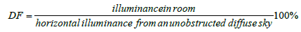 (A1)
(A1)
Recommended lighting luminance values for different functional activities were tabulated by the Bureau of Indian Standards [22], Illuminating Engineering society of North America (IES) [23], as well as by, the Commission International de I’ Éclair age (CIE) [24]. Further, the light factor is a measure of all the daylight reaching on an indoor reference point from the direct sky, external surfaces reflecting light directly to the point, and internal surfaces reflecting and inter-reflecting light to the point. Each of three components, when expressed as a ratio or percent of the simultaneous external illumination on the horizontal plane define respectively the sky component (SC), the external reflected component (ERC) and the Internal reflected component (IRC). The daylight factor on horizontal plane only usually taken as the working plane in a room is generally at 0.75 m level from the finished floor level; however the Day light factors in the vertical planes should also be considered when specifying day lighting values for special cases, such as daylight on a class room blackboard, wall hanger pictures or paintings in exhibition halls and sculptures in a museum.
DF=(SC+IRC+ERC) (A2)
Day Light Illumination=τ MF. GBC. (SC+IRC+ERC) × [(DS)/100] (A3)
where,
τ: Transmittance of the glazing
MF: Maintenance factor for conditions
GBC: Glazing bar correction
DS: Design sky.
The daylight factor has been calculated at a number of points on a regular grid with in the room of size 4.0 m × 6.0 m, a series of contours has been plotted or drawn which connects together those points which have the same daylight factor/intensity. Such daylight contours analyses how the daylight varies within the room. The quantitative analysis of daylight has been developed in order to investigate the daylight intensity level at different grid point, and further contours of the daylight has been developed to show the qualitative distribution pattern of light. Figure 1 shows the grid points in relation to x and y-axis of working plane and the position of the window opening. The same has been plotted in the form of graphs as per NBC-2005 and generated contours as derived by IES VE-2016 simulation and results have been discussed for appropriateness of a model and qualitative and quantitative analysis of the day light Illumination levels. The Design sky has been considered 10000 lux as per research paper [11], the results have been compared and found that the simulation results are inconformity and there is no variation more than 1%.

Figure 1: Room Module showing working plane and Day light Illumination grid.
Sky component
Sky component is the ratio of that part of the daylight illumination at a point on given plane, which is received directly from the sky as compared to the simultaneous exterior illumination on a horizontal plane from the entire hemisphere of an unobstructed clear design sky. The sky component at different points on working plane is analysed for different sizes of window by using the BIS/NBC 2005 to appreciate the indoor illumination levels. The values obtained are of rectangle open unglazed windows, with no external obstructions. The values are corrected by considering the window bars, glazing and external obstructions. The correction for window bars is carried by multiplying the values by a factor equal to the ratio of the clear opening to the overall. Where windows are glazed, the arrived sky component is reduced by about 10 to 20% provided the panes are of clear glass.
Internal and external reflected component
The component of day light factor contribute collectively by reflection from the inside surfaces, external obstructions and window area. It varies directly as per window area and inversely to the total area of internal surfaces. It depends on the reflection factors of the floor, wall and roof surfaces insides and of the ground outside. For rooms of white painted surfaces such as walls and ceiling and even for windows of normal sizes, the IRC will have a substantial value at points far away from the window. It was observed that the external obstructions will proportionally reduce the IRC and the same has been considered in the NBC 2005. As per NBC the perfect values of IRC, a specific method of evaluation of the same is given below. The values of the sky component corresponding to the portion of the window obstructed by the external obstruction are to be considered to achieve the ERC. The average IRC can be determined from the BIS internal reflection formula. The simplified form of this is:
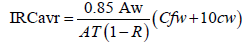 (A4)
(A4)
where,
0.85=Transmittance value of window glazing
Aw: window area
AT: total surface area (ceiling +floor +walls including windows)
ρfw: Average reflection of floor and all the walls excluding the window wall, below the plane at level mid height of the window .
ρcw: Average reflectance of the upper part and the ceiling of the above three walls.
C: A constant of value 78 when there is no external obstruction [BSI. (1975)]
R: The average reflection factor of all surfaces in the room (ceiling, wall and windows).
IES Simulation and NBC Analysis
The same room size of 4.0 × 6.0 m with the height of 4.0 m have been considered to analyze the different window openings through IES-VE 2016 for uniform overcast sky value of 10000 lux from 8.00 AM to 9.0 AM, luminance at Zenith, etc., the input data has been given below:
Design sky:
1. Uniform (overcast sky): Equivalent horizontal illuminance (design sky) 10000 lux (8:00 am-9:00 am) Luminance at zenith Lz (Cd/ sqm)-4337.
2. CIE (overcast sky): Lz(Cd/sqm) obtained from date , longitude and latitude (Table 1)
| 7 h | 8 h | 9 h | 10 h | 11 h | 12 h | 13 h | 14 h | 15 h | 16 h | 17 h | 18 h |
|---|---|---|---|---|---|---|---|---|---|---|---|
| 1547 Lux | 5708 Lux | 9385 Lux | 12327 Lux | 14333 Lux | 15266 Lux | 1506 3Lux | 13738 Lux | 11380 Lux | 8152 Lux | 4272 Lux | 5 Lux |
Table 1: Ground ambient lux from 7 am to 5 pm ranges.
Reflectance: 70%
Maintenance factor: 0.9
Typology of illuminance: Planar (horizontal)
Materials Reflectance
External Wall (ext) {new concrete (traditional)}: 0.371
Wall (int) {new concrete with white Portland cement}: 0.718
Roof (ext) {aged concrete}: 0.250
Roof (int) {white gypsum}: 0.900.
Results and Discussion
Effect of window area by varying height of a window for a quantitative study of performance of illumination levels for various window areas, computations have been performed corresponding to the window area variations, width variations, height variations and placement of windows for room module of 4.0 m × 6.0 m × 4.0 m with 0.75 m sill height of window. The room module is divided in the grid form to define the various location points to arrive the sky component, % of DF and intensity of illumination at every point of the grid. Figure 1 shows the grid on working plane in relation to the X and Y axis, accordingly the illumination contours and corresponding contour mapping has been plotted. The input parameters are given below:
Design daylight=10000 lux (as per perze Model – [20])
Area of window=Aw
Room size: 4.0 m × 6.0 m
Height of the room=4.0 m
Sill level=0.75 m, 0.9 m
Lintel level=2.1 m, 2.55 m
Width of the window=1.00 m, 1.25 m, 1.50 m, 1.75 m, 2.0 m, 2.25 m, 2.5 m, 3.0 m
Height of the window=1.35 m and 1.8 m
Transmittance of window glazing Ct=0.85
Coefficient of external obstruction Cb=78
Cc=10
External reflected component ERC=0.1
Total surface area (ceiling +floor +walls including windows) AT=148 m2
Reflection coefficient of the floor; Rf=0.2; Rwin=0.15
Reflection coefficient of the window; Rwin=0.15
Reflection coefficient of the wall; Rwin=0.7
Reflection coefficient of ceiling; Rc=0.7
Transmittance of the glazing τ=0.85
Maintenance factor for conditions MF=0.7
Glazing bar correction GBC=0.9
Sky component=As per NBC-2005.
Figures 2-4 show the variations of illumination levels/contours in a room module of 4.0 m × 6.0 m with respect to the varying window widths keeping the height is of 1350 mm constant with sill height of 750 mm. It is observed from Figures 2-4, the illumination levels at the corners of the building module having 101, 105 and 111 lux, but the spread value of illumination shows 169, 156 and 146 lux respectively. Even though the window area is lesser but the spread is comparatively impressive at corners of working plane and the only variation is of width (i.e., 1.75 m to 2.50 m wide window). It is clear that the wider the window, the spread is more uniform and hence, is recommended in places where functional activity requires spread of light that is more uniform in nature. The window W2 of size 2.25 m × 1.35 m with sill of 0.75 m having area of 3.04 m2 is showing an impressive spread of illumination levels for the building module of 5.0 m × 6.0 m. Hence the 3.04 m2 window with the said size is considered as an appropriate opening size in term of the day lighting for general purpose with respect to the size and area of the room.

Figure 2: Illumination levels on working plane of window W1 (1.75 m × 1.35 m).

Figure 3: Illumination levels on working plane of window W2 (2.25 m × 1.35 m).

Figure 4: Illumination levels on working plane of window W3 (2.50 × 1.35 m).
Figures 5 and 6 shows the illumination levels of window W4 (2.0 m × 1.8 m) and W5 (2.0 × 1.35 m) and it is observed the illumination intensity of W4 at corners of the room is 140 lux whereas for window W5 gives only 90 lux. It can be seen at room coordinates of (4, S4) the illumination levels are in range of 200-300 and 100-200 for W4 and W5 respectively. The varying height of window indicates that lengthier the window the illumination penetration is more, suitable for double loaded corridors, kitchen, booking counters and reading room of a library with reference to the desired daylight illumination levels workable as per interior layout.

Figure 5: Day light Illumination levels on working plane (W4 =2.00 × 1.80).

Figure 6: Day light Illumination levels on working plane (W5=2.00 × 1.35).
It has been analysed to assess the illumination level of W1 window splitting in to two parts (Wb1-0.75 m × 1.35 m) and Wal-1.0 m × 1.35 m) and keeping the same area of the window and locating it as shown in (Figure 7). Two windows of Wb1 (0.75 m × 1.35 m) and Wa1 (1.00 m × 1.35 m) are considered for locating side-by-side on vertical plane walls with constant sill level of 0.75 m and lintel level of 2.10 m to analyse the illumination levels on working plane. The window positioning considered at diagonal corners as shown in the Figure 7 to appreciate the daylight performance. The resultant illumination levels are given in the form of corresponding illumination contours shown in Figure 7. A single window having (equal to two window opening area) the opening area of 2.3625 m2 with the size of W1-1.75 m × 1.35 m placed at middle of the 6 m wide vertical plane with the same sill level of 0.75 m considered for illumination analysis on working plane of the building. The daylight illumination on working plane corresponding to the room grid or coordinates; the same can be seen in the form of illumination contours in Figure 8. In comparison to illumination levels shown in both the daylight contours, it is found that the daylight illumination lux on working plane nearer to the opposite side wall of the window is having 90 to 120 lux for single window configuration whereas for double window configuration the illumination contours are in the range of 100 to175 lux. Besides, the uniform spread of 100 to 175 lux can be seen in the Figure 7 for double window configuration. It is noted that the double window configuration works better for spread of illumination instead one window of the same size so the double window configuration is performed much better hence this configuration can be considered wherever possible [25].

Figure 7: Day light Illumination contours on the working plane –option I.

Figure 8: Day light Illumination contours on working plane of window Wa4 (1.750 × 1.35 m).
The double window configuration is further analysed with the variation of locating a window on vertical plane at the centre as an option-II and locating a window at the opposite plane at diagonal as an option-III shown in (Figure 9). The Illumination contours of Option-III are quite impressive in terms of spread and enhanced illumination levels on working plane hence it an appropriate design configuration for window placement among all. Besides, varying window sizes for the said room size have been analysed along with the daylight illumination levels and the same has been tabulated for middle and corners places of the room to verify the spread and penetration lighting levels as shown in Table 2.

Figure 9: Day light Illumination contours on working plane for option-II and option-II.
| Item | Lux | Lux | Lux | Lux | Lux | Size |
|---|---|---|---|---|---|---|
| 1 m | 2 m | 3 m | 4 m | 5 m | - | |
| Illumination levels at corners | ||||||
| W6 | 152.65 | 137.04 | 113.14 | 87.57 | 78.32 | 1.0 m × 1.8 m |
| W4 | 262.66 | 184.87 | 183.89 | 154.69 | 138.95 | 2.0 m × 1.8 m |
| W7 | 342.61 | 291.11 | 239.95 | 221.88 | 192.34 | 3.0 m × 1.8 m |
| Illumination levels at middle axis | ||||||
| W6 | 353.15 | 241.29 | 173.93 | 96.64 | 95.42 | 1.0 m × 1.8 m |
| W4 | 594.18 | 403.31 | 275.45 | 209.52 | 173.77 | 2.0 m × 1.8 m |
| W7 | 875.29 | 543.53 | 410.65 | 315.93 | 225.59 | 3.0 m × 1.8 m |
| Illuminmation levels at corners | ||||||
| Wa1 | 97.62 | 84.53 | 73.97 | 63.89 | 54.56 | 1.0 m × 1.35 m |
| Wa5 | 197.66 | 136.37 | 122.1 | 115.52 | 90.11 | 2.0 m × 1.35 m |
| Wa8 | 328.11 | 200.21 | 181.64 | 170.67 | 139.43 | 3.0 m × 1.35 m |
| Illumination levels at middle axis | ||||||
| Wa1 | 346.23 | 311.62 | 150.63 | 72.62 | 68.49 | 1.0 m × 1.35 m |
| Wa5 | 627.1 | 314.75 | 260.72 | 157.48 | 136.62 | 2.0 m × 1.35 m |
| Wa8 | 840.95 | 422.23 | 305.57 | 241.24 | 172.69 | 3.0 m × 1.35 m |
Table 2: Day light illumination levels at a room size of 6.0 × 4.0 m for varying window sizes.
Conclusion
It is essential and crucial to derive the appropriate window sizes for achieving desirable illumination levels required for various functional considerations of a space design. The first of the new computation tools for daylight was developed by Waldram during the 1920's, acknowledged as the ‘Waldram diagram’. This allowed the first precise calculation of the amount of light entering a room. The tools extensively developed in due course of time to give accurate results, i.e., the NBC- 2005 and IES VE 2016 simulation has shown perfect conformity to each other as elaborated in the paper. The window opening design is a critical component in a building in order to conserve illumination energy with respect to desirable sizes and the functional utility of the space. This has to be dealt with adequate scientific knowledge to save illumination energy by appropriate daylight levels on working plane.
This can be further studied by integrating with thermal comfort and number of required air change per hour.
References
- Bansal NK (1999) Emerging trends for energy efficiency in Buildings. International Journal of Renewable Energy Engineering 1: 3
- Djamila H, Ming CC, Kumaresan S (2011) Estimation of exterior vertical daylight for the humid tropic of Kota Kinabalu city in East Malaysia, Renewable Energy 36: 9-15.
- Diéguez’ AP, Gentile N, Wachenfelt HV, Duboisba MC (2016) Daylight Utilization with Light Pipe in Farm Animal Production: A Simulation Approach. Journal of Day lighting 3: 1-11.
- Choi JH, Beltran LO, Kim HS (2012) Impacts of indoor daylight environments on patient average length of stay (ALOS) in a healthcare facility, Building and Environment 50: 65-75.
- Zain-Ahmed A, Sopian KMY, Othman MY, Sayigh AA, Surendran P (2002) Daylighting as a passive solar design strategy in tropical buildings: a case study of Malaysia. Energy Conversion and Management 43: 1725-1736.
- Chauvel P (1982) Glare from windows: Current views of the problem. Lighting research and technology 14: 31-46.
- Mahdavi A, Rao SP, Inangda N (2013) Orientation Effects on Daylighting in High-Rise Office Buildings in Malaysia: a simulation study, in International Conference on Alternative Energy in Developing Countries and Emerging Economies. Bangkok, Thailand.
- Ahmad M, Lim YW, Dilshan RO (2010) Empirical validation of daylight simulation tool with physical model measurement. American Journal of Applied Sciences 7: 1426-1431.
- Lim YW, Heng CYS (2016) Dynamic internal light shelf for tropical day lighting in high-rise office buildings, Building and Environment 106: 166
- Ramesh S (2018) Assessment of design sky for design of day lighting in buildings in central capital region. International Journal of Latest Trends in Engineering and Technology 9: 148-154.
- Kaushik SC, Sodha MS, Bansal PK, Bharadwaj SC (1982) Solar thermal modelling of non-airconditioned building: Evaluation of overall heat flux. Energy Research 6: 143-160.
- Chandra M (1996) Luminous efficacy of solar radiation and evaluation of natural illumination. Energy Convers Mgmt 37: 1632-1634.
- Kaushik SC, Tiwari GN, Nayak JK (1988) Thermal control in passive solar building. Go-Environ Academia press, Jodhpur.
- Mchugh JR (1995) Thesis-Day lighting design via Monte Carlo’ Colorado state university. Fort Collins, Colorado.
- Ramesh S (2015) Initiatives in Climate Responsive and Energy Efficient Architecture. First International Conference for Sustainable Development and Management, promoted by Hong Kong University of Science and Technology.
- Ramesh S (2017) Analyzing Vernacular Sustainable Design Principles - A Case Study of a Vernacular Dwelling in Godavari Region of Andhra Pradesh India. International Journal of Emerging Trends in Science and Technology 4: 5010-5017
- TERI, Min. of non-conventional Energy Sources Energy-efficient buildings in India TERI and MNEC, 2001.
- Bansal NK, Cook Jeffrey (2001) Sustainability through Building. Omega Scientific Publishers, India
- Gillette G, Pier Point W, Treado S (1984) General Illuminance Model for Daylight Availability. Journal of the Illuminating Engineering Socity 330-340.
- McCluney R (1998) Advance fenestration and day lighting systems. Proceedings of international conference on Day lighting technologies for energy efficiency in buildings ottava, Canada.
- The Bureau of Indian Standards (BIS), Guidelines for day lighting 1989.
- IES, Dilaura DL (1984) Recommended practice for the calculation of Daylight availability. Journal of the Illuminating engineering society 13: 381-392.
- Commission International de L’Elairage, Standardization of Luminance distribution on clear skies CIE publication.
- Perez R, Ineichen P, Seals R (1990) Modeling Daylight availability and Irradiance Components from Direct and Globle Irradiance Solar Energy 44: 271-289.
Citation: Srikonda R (2018) Window Sizing for Daylighting for Non-Airconditioned Buildings in Andhra Pradesh, India. J Archit Eng Tech 7: 212. DOI: 10.4172/2168-9717.1000212
Copyright: © 2018 Srikonda R. This is an open-access article distributed under the terms of the Creative Commons Attribution License, which permits unrestricted use, distribution, and reproduction in any medium, provided the original author and source are credited.
Select your language of interest to view the total content in your interested language
Share This Article
Recommended Journals
Open Access Journals
Article Tools
Article Usage
- Total views: 6963
- [From(publication date): 0-2018 - Dec 20, 2025]
- Breakdown by view type
- HTML page views: 5977
- PDF downloads: 986