A High Resolution Measurement of Foreshocks for the Prediction of Earthquakes
Received: 06-Sep-2012 / Accepted Date: 27-Sep-2012 / Published Date: 01-Oct-2012 DOI: 10.4172/2157-7617.1000116
Abstract
It has been recently reported that there is a very strong relationship and well defined similarities in the vibration pattern of foreshocks, main shock and aftershocks which can be used for the prediction of earthquake. It has also been established that foreshocks are the best accredited forecaster of earthquakes. However, the foreshocks consist of an adverse combination of extremely high contents of velocity and acceleration superimposed over a very low frequency wave. Therefore, the existing low resolution accelerometers and seismometers are incapable to get an insight of the signatures of these foreshocks. In the proposed method, a fast rotating magnetic field (RMF) is used to measure the velocity and acceleration of vibrations at high resolution and accuracy. To simulate the foreshocks, a microprocessor based rocking vibration arrangement is used which generates vibrations similar to the foreshocks. These vibrations are mechanically transmitted to the rotor of a synchro. According to the movement of the rotor of synchro, the RMF generates voltage signals at the rotor output and thereby a broad spectrum of square pulses is produced with the help of a logic circuit. Consequently, all possible values of instantaneous velocity and acceleration of foreshocks are obtained, in terms of pulse widths. Hence, it gives a deep insight to recognize the distinct features of signature of foreshocks. This would help in an accurate prediction of earthquakes. The measurement is also simultaneously communicated to a PC for monitoring and remote sensing. The proposed system is simply coupled with the conventional standard spring attachment system to measure the actual foreshocks. A number of such units may be placed at different earthquake prone areas for centralized monitoring.
Keywords: Foreshocks; Earthquake predictor; Synchro based measurement; Seismic vibration transducer
8645Introduction
Making a system sustainable and more resilient to disasters is a complex venture, for which there is no quick solution. The disaster reduction to this challenge requires a rigorous effort and a wide range of solutions-oriented multidisciplinary, multi-institutional, research and talents. The earthquake is one of the prime causes of natural disasters, human loss, technological disasters, and damage to heavy building structures, and electric power and water delivery system. An accurate prediction of earthquake will minimize the loss of life, severe injuries, and disruption of important services. Several experiments, based on the change of electric current in dielectric media and soil, have been carried out in Greece, to predict the earthquakes [1-4]. The VAN method also gives a good prediction of earth quake to vacate a certain area. However, the large numbers of dipoles (buried at the depth of 2 meters) are required at a distance of 100 meters to 10 km. Therefore, large connecting wires, required to supply the signal to a difference amplifier, make the system costly and intricate [5]. Attempts were also made in Japan, for the prediction of earthquakes, which were based on chemical changes in mineral water. Nonetheless the technique is very expensive and complex for its realization [6,7].
Generally, before any earthquake, there are foreshocks with hidden signatures of velocity and acceleration. The researchers have explored that there is a strong correlation (in seismicity rate and stacked amplitude etc) and physical linkage in the foreshocks, main shock and aftershocks for the prediction of earthquakes [8-12]. Moreover the foreshocks consist of very low frequency wave but high frequency spikes are superimposed, which have extremely high instantaneous velocity and acceleration. Hence, due to this adverse combination, the existing low resolution accelerometers and seismometers are unable to get an insight of signatures of these foreshocks [13]. The fact has been established recently that the foreshocks are best accredited forecaster of earthquakes [14]. Moreover, the foreshocks and aftershocks are having a similar and well defined pattern of velocity and acceleration, within the error of measurement. This thinking has been supported by the seismic response time histories and comparison of measured and identified data records of seismic vibrations [15]. The findings have also revealed that there is very much resemblance in the pattern of foreshocks and main shock. However, the present measurement of foreshocks with resolution in seconds, does not give a deep insight of the signatures of these small seismic vibrations [14,15]. Various techniques, for measuring the velocity and acceleration of foreshocks and main shock, are also proposed in the literature. However, the resolution of measurement of these methods is of the order of tens of seconds. Hence these methods are still slow, less accurate, and unreliable for the prediction of earthquakes [16-19].
In the proposed method, a microprocessor based vibration generating system is developed to mechanically simulate the foreshocks. The system vibrates the rotor of a synchro back and forth. A balanced three-phase ac current, in the three-phase stator windings of synchro, generates a very fast rotating magnetic field (RMF) in the air gap [20,21]. The movement of rotor due to vibration system generates an emf, of variable amplitude and frequency in the rotor circuit of synchro. Consequently a spectrum of pulses is produced corresponding to the velocity of vibrations. Since the RMF completes its revolution in the air gap within few tens of milliseconds (ms), therefore, even the slight movement of the rotor of synchro due to vibration generating system immediately changes the frequency of the induced emf in the rotor. Thus, the measurement of instantaneous velocities of these vibrations becomes possible due to high speed of RMF. This fast measurement gives a very high resolution of measure and for an accurate prediction of earthquake.
Theory
A synchro is used to measure the speed and angle of a rotating machine. It is also considered as a rotary electrical transformer. However, the physical construction of synchro is similar to an electric motor. The three-phase, star-connected stator windings of synchro are excited by a three-phase alternating current to produce an RMF in the air gap, which rotates by a speed of NS, which is given by
 (1)
(1)
where, FS is the frequency of voltage or current at stator windings, in Hz and P is the number of poles [22].
If the rotor speed of synchro is NR rpm, the relative speed or the slip is (NS–NR), in the direction of NS. However, if the direction of rotation is opposite, the slip becomes (NS + NR). The frequency of the voltage, induced in the rotor circuit is given by
 (2)
(2)
and,
 (3)
(3)
Since, the number of poles (P) and the supply frequency (FS) are constant; the frequency of the induced voltage in the rotor circuit depends on the rotor speed, NR. When the rotor of the synchro is stationary, it acts as a transformer. Therefore the frequency of the rotor voltage (FR) and stator voltage are equal (FR=FS). However, when the rotor rotates, the frequency of the induced voltage is proportional to the slip (NS + NR), where NS is constant. Here, the speed of the rotor of synchro is few rpm, corresponding to the foreshocks vibrations. Whereas, the speed of RMF is 3000 rpm for a supply frequency of 50 Hz. Consequently, the measurement becomes very fast and accurate and the resolution becomes very high.
Rialization
In the proposed method, a synchro is used for the measurement of velocity and acceleration of mechanically simulated foreshocks. The rotor of synchro is attached with a microprocessor based vibration generating system (Figure 1). A high resolution oscillator supplies a 50 Hz voltage signal to a centre-tapped transformer whose output is then applied to a phase splitting circuit, with an RC network (R=100 kΩ and C=0.1μF), to provide a balanced three-phase, 50 Hz voltages V1, V2, and V3 (Figure 2). These three voltages are reduced to about 100 mV (V4, V5, and V6), and then fed into three power amplifiers (LM 384N). The outputs of these three amplifiers, V7, V8 and V9 (Figure 3), are applied to the stator windings of synchro, to generate a sinusoidal voltage signal, VR with frequency, FR in the rotor winding of synchro (Figure 4).
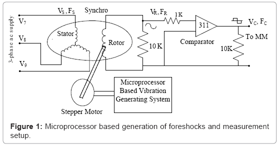
Figure 1: Microprocessor based generation of foreshocks and measurement setup.
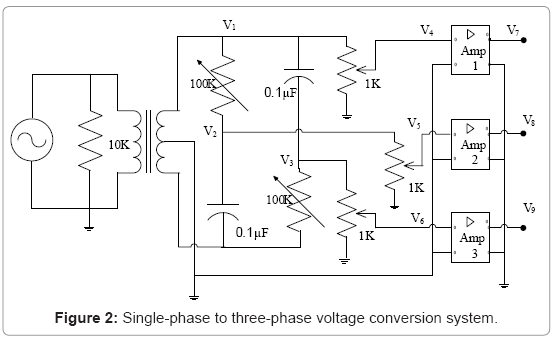
Figure 2: Single-phase to three-phase voltage conversion system.
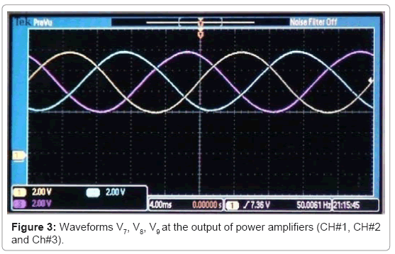
Figure 3: Waveforms V7, V8, V9 at the output of power amplifiers (CH#1, CH#2 and Ch#3).
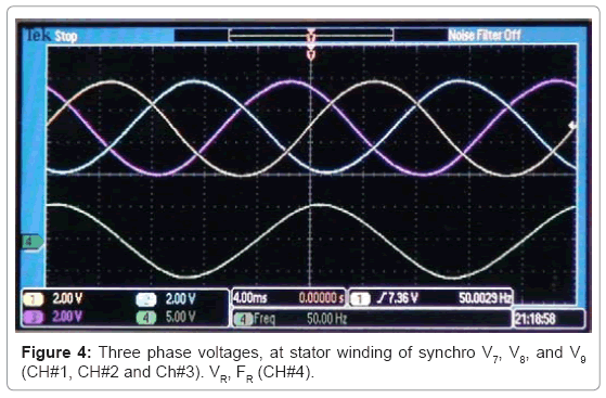
Figure 4: phase voltages, at stator winding of synchro V7, V8, and V9 (CH#1, CH#2 and Ch#3). VR, FR (CH#4).
Experimental Results
Here, a microprocessor based vibration generating system is developed to simulate the foreshocks. The microprocessor is programmed to vibrate a stepper motor to generate the vibrations, corresponding to foreshocks, in the range of -10 cm/s to +10 cm/s, with a frequency of about 2 Hz. The stepper motor is attached to the rotor of a synchro. The vibrations generated by the stepper motor are transmitted to the rotor of synchro. As the rotor of synchro vibrates, the frequency of rotor voltage in the rotor circuit changes. Therefore, a pulse train of different pulse-width is produced which corresponds to the instantaneous velocity of foreshocks. The proposed system is simply attached with the conventional standard spring attachment system to measure the actual foreshocks.
Vibration system at rest
As long as the vibration system is at rest, the velocity of rotor of synchro is zero. The synchro works as a transformer. The frequency of rotor voltage, FR is same as that of stator voltage, FS. The signal, VR is now applied to a fast voltage comparator to produce a rectangular waveform, VC of frequency, FC, where FC= FR, as shown in Figure 5. The positive edge of signal, VC triggers a mono-stable multi-vibrator (MM) as shown in Figure 6. The MM produces an output; A and its complement A´ of stable positive/negative widths of 10 ms. The output of NAND gate, G becomes HIGH (Logic 1) as the positive and negative widths of signal VC and A´ are equal. This is also given by
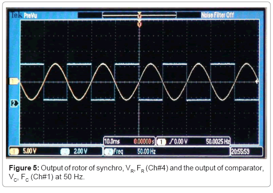
Figure 5: Output of rotor of synchro, VR, FR (Ch#4) and the output of comparator, VC, FC (Ch#1) at 50 Hz.
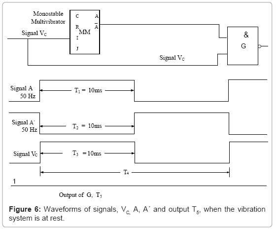
Figure 6: Waveforms of signals, VC, A, A´ and output T5, when the vibration system is at rest.
 (3)
(3)
where,
FC=frequency of signal VC at comparator’s output (FC = FR).
T1=positive width of signal A
T2=negative width of signal A’
T3=positive width of the signal VC
T4=time period of the signal VC
T5=negative width of the pulse at the output of G
Also, T5=T3-T2 (4)
Vibration system at rest
FC=FR=FS=50 Hz
T4=(1/FC)=20 ms
T3=(T4/2)=(1/2FC)=10 ms
T2=10ms=0.01 seconds
T5=T3-T2
T5 =10-10
T5=0
Hence the output of gate G= HIGH (Logic 1)
The waveforms VR, VC, A´ and T5 are also shown in the DSO records (Figure 7)
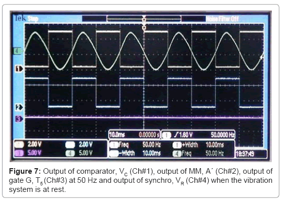
Figure 7: Output of comparator, VC (Ch#1), output of MM, A´ (Ch#2), output of gate G, T5 (Ch#3) at 50 Hz and output of synchro, VR (Ch#4) when the vibration system is at rest.
Vibration system in motion
When the microprocessor vibrates the stepper motor, the rotor of the synchro moves back and forth due to its attachment with the stepper motor. For a 50 Hz, 2 pole synchro, the RMF revolves at a very fast speed of 3000 rpm; in the air gap. Hence an infinitesimal angular movement of the rotor of synchro generates a voltage, of frequency, FR in its rotor circuit. The frequency of this voltage varies in the vicinity of 50 Hz, depending on the direction of motion of rotor due to vibrations.
For every instantaneous change in the movement of rotor, a pulse appears within 10 ms, with a pulse width, corresponding to the velocity of vibrations (Figure 8). The time period of signal VC, at the output of comparator, T4 (or 1/FC) varies instantaneously. Consequently its positive width, T3 also varies. The positive edge of signal VC triggers an MM to generate a signal, A and its compliment A´ with constant positive and negative widths of 10 ms (T1 and T2). When the signals VC and A´ are supplied to gate G, a pulse is produced at its output on every falling edge of signal VC, with a negative width, T5 (Figure 9 and Figures 10a-10d). The widths of these pulses are proportional to the instantaneous velocity of vibrations (or instantaneous velocity of the rotor of synchro). The pulse, with maximum negative width, is proportional to the peak velocity of vibrations. The instantaneous velocity of these vibrations with various parameters is calculated as follows.
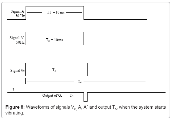
Figure 8: Waveforms of signals VC, A, A´ and output T5, when the system starts vibrating.
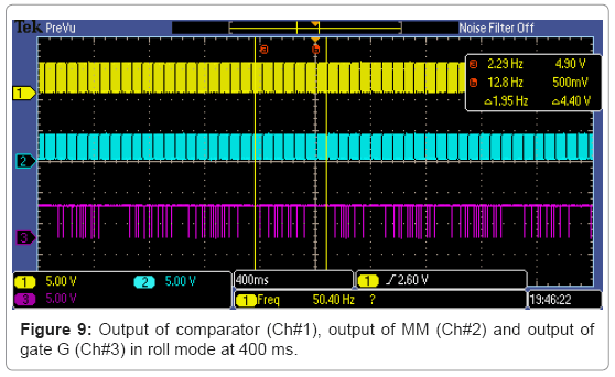
Figure 9: Output of comparator (Ch#1), output of MM (Ch#2) and output of gate G (Ch#3) in roll mode at 400 ms.
 (4)
(4)
The pulse width T5 of instantaneous pulses are given by (4)
T5=T3-T2 (4)
T5=(1/2FC)-0.01 (5)
 (6)
(6)
From (3) and (6), the instantaneous speed NR, proportional to the width of any pulse, obtained at the gate G is given by
 (7)
(7)
For, P=2 and FS=50 Hz, from (7),
 (8)
(8)
The instantaneous velocity (V) of the foreshocks is given by
V=W×R
 (9)
(9)
where,
W=Angular speed of rotor of synchro in radian per second.
R=Radius of the rotor of synchro=0.912 cm
Now from (9), (8) and (10)
V=0.0955×NR (10)
and  (10)
(10)
Figure 9 and Figures 10a-10d show the spectrum, corresponding to the velocity of vibrations (equivalent to foreshocks) observed and recorded by DSO. These results are also given in Table 1. It is also evident from these results that even within one second, the variation of velocity is quite significant, which is generally not sensed and recorded by the conventional accelerometers. In one second, this spectrum shows all possible values of instantaneous velocity of foreshocks, in terms of pulse widths, within 10 ms resolution. Therefore the measurement for the pattern of foreshocks becomes extremely fast and accurate, which will be helpful to recognize the unique signatures of these vibrations.
| S. No | T5 (µs) =T3 – T2 | Velocity of Foreshocks (cm/s) | Acceleration of Foreshocks (cm/s2) |
| 1 | 0 | 0 | 0 |
| 2 | 16.17 | 0.59 | 29.5 |
| 3 | 32.90 | 1.07 | 24 |
| 4 | 44 | 1.38 | 15.5 |
| 5 | 80 | 2.40 | 51 |
| 6 | 160 | 4.80 | 120 |
| 7 | 220 | 6.29 | 74.5 |
| 8 | 360 | 10.08 | 189.5 |
| 9 | 272 | -7.71 | -118.5 |
| 10 | 153.7 | - 4.46 | -162.5 |
| 11 | 49.52 | - 1.54 | -146 |
| 12 | 38 | -1.27 | -13.5 |
| 13 | 17.13 | -0.618 | -32.6 |
Table 1: Results for the measurement of foreshocks.
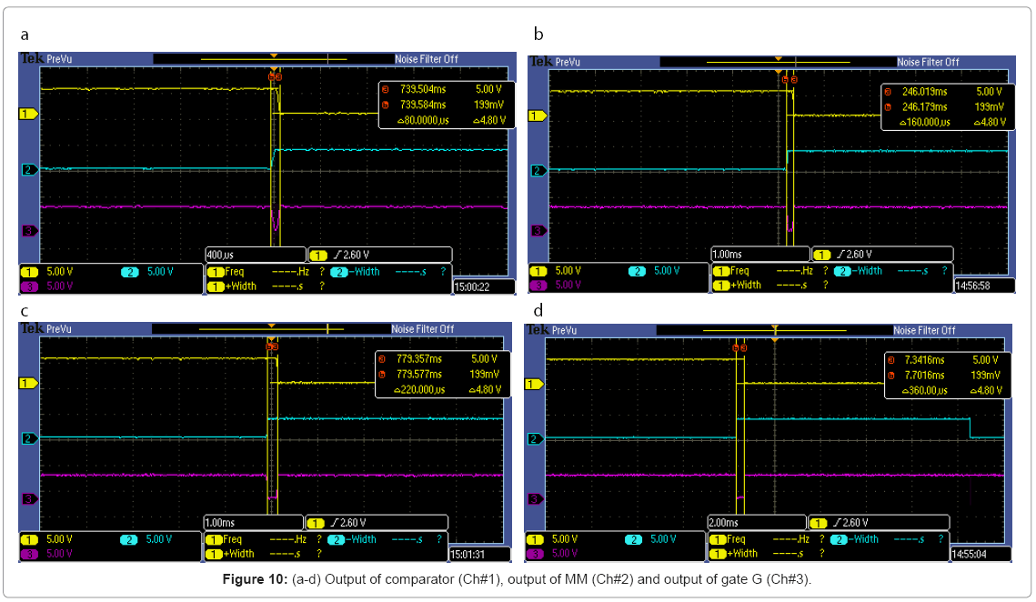
Figure 10: (a-d) Output of comparator (Ch#1), output of MM (Ch#2) and output of gate G (Ch#3).
An average value of velocity of these vibrations is directly obtained in terms of dc voltage, when the pulse train (output of gate G) is applied to an averaging circuit with amplifier. Moreover, the instantaneous values of acceleration of these foreshocks are also calculated by using the difference of velocities of two successive pulses within a time period of 20 ms.
Conclusion
A novel technique for the measurement of foreshocks is proposed. A microprocessor based vibration generating system is developed to mechanically generate the vibrations, equivalent to foreshocks, in the range of -10 cm/s to +10 cm/s, with a frequency of about 2 Hz. These vibrations are transmitted to the rotor of a synchro. A high speed RMF provides fast measurement of foreshocks with high accuracy and resolution. A spectrum of pulses with different pulse width, corresponding to instantaneous velocity the foreshocks, is obtained which shows the pattern of the foreshocks. This output signal is also converted to an analog output voltage by averaging circuit and an amplifier to show the nature of vibrations. The existing and conventional instruments measure the velocity of these vibrations with resolution of seconds, whereas due to fast measurement, the proposed scheme gives a high measurement resolution of 10 ms. Consequently, it provides a deep insight to recognize the signature of these vibrations, which will help in an accurate prediction of earthquakes to safeguard the heavy losses. The proposed system has to be simply coupled with the conventional standard spring attachment system to measure the actual foreshocks. A number of such units at earthquake prone areas may be placed and connected to supervisory monitoring centre for a continuous monitoring of seismic vibrations. The data from these units may be remotely sensed, monitored and simultaneously communicated for the centralized monitoring through the internet.
References
- Varotsos PA, Sarlis NV, Skordas ES (2011) Natural Time Analysis: The new view of time. Precursory Seismic Electric Signals, Earthquakes and other Complex Time-Series (Springer-Verlag, Berlin Heidelberg).
- Varotsos P, Sarlis N, Lazaridou M, Kapiris P (1998) Transmission of stress induced electric signals in dielectric media. J Appl Phys 83: 60-70.
- Varotsos P, Alexopoulos K, Nomicos K, Lazaridou M (1986) “Earthquake prediction and electric signals,"Nature 322: 120.
- Varotsos P, Alexopoulos K, Nomicos K (1982) "Electrotelluric precursors to earthquakes,†Proc. 1982, The Academy of Athens Conf 341-363.
- Lazaridou-Varotsos MS (2011) Earthquake Prediction by Seismic Electric Signals. The success of the VAN method over thirty years. (Springer-Verlag, Berlin Heidelberg).
- King CY, Evans WC, Presser T, Husk R (1981) Anomalous chemical changes in well water and possible relation to earthquakes. Geophys Res Lett 8: 425-428.
- King CY, Koizumi N, Kitagawa Y (1995) Hydrogeochemical anomalies and the 1995 Kobe earthquake. Science 269: 38-39.
- Felzer KR, Abercrombie RE, Ekstrom G (2004) A common origin for aftershocks, foreshocks, and multiplets. Bulletin of the Seismological Society of America 94: 88-98.
- Helmstetter A, Sornette D, Grasso JR (2003) Mainshocks are aftershocks of conditional foreshocks: How do foreshock statistical properties emerge from aftershock laws. J Geophys Res 107.
- McGuire JJ, Boettcher MS, Jordan TH (2005) Foreshock sequences and short-term earthquake predictability on East Pacific Rise transform faults. Nature 434: 457-461.
- Peng Z, Vidale JE, Ishii M, Helmstetter A (2007) Seismicity rate immediately before and after main shock rupture from high frequency waveforms in Japan. J Geophys Res 112.
- Zhuang J, Christophersen A, Savage MK, Vere-Jones D, Ogata Y, et al. (2008) Differences between spontaneous and triggered earthquakes: Their influences on foreshock probabilities. J Geophys Res 113.
- Rupakhety R, Sigbjornsson R (2010) A note on the L’Aquila earthquake of 6 April 2009: Permanent ground displacements obtained from strong-motion accelerograms. Journal of Soil Dynamics and Earthquake Engineering 30: 215-220.
- Brodsky EE (2011) The spatial density of foreshocks. Geophysical Research Letters 38: 1-6.
- Gong M, Sun J, Kashima T, Xie L (2010) Parameter Identification of a 9-Story Building for Earthquake Damage Detection. 3rd International Congress on Image and Signal Processing 3650-3654.
- Mandal P (2009) Crustal shear-wave splitting in the epicentral zone of the 2001 Mw 7.7 Bhuj earthquake, Gujarat, India. Journal of Geodynamics 47: 246-258.
- Stephenson WR (2005) Late resonant response at Wainuiomata, New Zealand, during distant earthquakes. Journal of Soil Dynamics and Earthquake Engineering 25: 187-196.
- Durukal E (2002) Critical evaluation of strong motion in Kocaeli and Du¨zce (Turkey) Earthquakes. Journal of Soil Dynamics and Earthquake Engineering 22: 589-609.
- Taflampas IM, Spyrakos CC, Koutromanos IA (2009) A new definition of strong motion duration and related parameters affecting the response of medium-long period structures. Journal of Soil Dynamics and Earthquake Engineering 29: 752-763.
- Arif SJ, Laskar SH (2011) A rotating magnetic field based high resolution measurement of velocity and acceleration of seismic vibrations. The Indian Patent Office Journal 7116.
- Arif SJ, Asghar MSJ, Imdadullah A (2012) Very fast measurement of low speed of rotating machines using rotating magnetic field. IEEE Trans Instrum Meas 61: 759-766.
- Morris AS (2001) Measurement and Instrumentation Principles, (3rdedn) USA: Butterworth-Heinemann.
Citation: Arif SJ, Asghar MSJ, Khan KF (2012) A High Resolution Measurement of Foreshocks for the Prediction of Earthquakes. J Earth Sci Climate Change 3: 116. DOI: 10.4172/2157-7617.1000116
Copyright: ©2012 Arif SJ, et al. This is an open-access article distributed under the terms of the Creative Commons Attribution License, which permits unrestricted use, distribution, and reproduction in any medium, provided the original author and source are credited.
Select your language of interest to view the total content in your interested language
Share This Article
Recommended Journals
Open Access Journals
Article Tools
Article Usage
- Total views: 16149
- [From(publication date): 7-2012 - Nov 22, 2025]
- Breakdown by view type
- HTML page views: 11245
- PDF downloads: 4904