A Modified Kinetic Reaction Scheme for Claus Reaction Furnaces in Oil Refineries
Received: 31-Jul-2018 / Accepted Date: 13-Aug-2018 / Published Date: 17-Aug-2018 DOI: 10.4172/2576-1463.1000215
Keywords: Kinetic modeling; Optimization; Reaction furnace; Oil refineries; Claus unit
Introduction
Acid gas was mainly composed of carbon dioxide (CO2) and hydrogen sulfide (H2S) [1]. These two problematic compounds must be removed from natural gas in order to appropriate it for further usages as fuel and other applications. Sulfinol, Rectisol, Selexol, Flour and amine extraction processes are some methods of sweetening acid gas [2]. Processing of acid gas in an amine extraction process is one of the important processes for carbon dioxide and hydrogen sulfide removal. In amine treatment unit, absorption of CO2 and H2S is conducted through passing the acid gas over alkanolamine solutions [3]. Sweetened acid gas, due to stringent environmental regulations must be processed to reduce further hydrogen sulfide. Sulfreen, Unisulf, Takahax, and modified Claus processes are some options to reduce hydrogen sulfide contents of acid gases [4]. Nowadays, a new technology to convert acid gas to syngas (AG2STM) is proposed [5], but the modified Claus process is still more common than others due to higher sulfur conversion and operation at higher H2S concentration and capacity [6]. This implies the importance of declaring a kinetic model for its description and optimization of its operation for better performance and higher conversion, consequently lower sulfur emissions.
Elements of sulfur are produced by the partial oxidation of H2S in simple overall reaction as follows [1]:
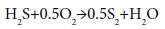 (1)
(1)
The modified Claus process is conducted at two steps named thermal and catalytic stages. The thermal stage includes conversion of one-third of H2S in acid gas feed to sulfur elements. This step is conducted at Reaction Furnace (RF) and Waste Heat Boiler (WHB). The Partial combustion of hydrogen sulfide and the conversion to sulfur dioxide occur in the RF that is made as a refractory lined cylindrical vessel. Inlet acid gas to the RF has a 130-180 kPa pressure and is oxidized with an appropriate quantity of air. The required air is determined based on a 2:1 ratio of H2S:SO2 in the reactor effluent. The combustion of acid gases in the RF is performed at the temperature ranges of 975°C -1300°C and gas residence times of 0.5-2.0 s [7]. Combustion products of the RF enter the WHB, equipment after the RF. The WHB is a shell and tube heat exchanger cooling hot gases of the RF to approximately 230°C-370°C and generating high pressure steam on the shell side [7]. Occurrence of recombination reactions is one of the main features of the WHB from a reaction chemistry viewpoint [8].
The following reaction for the partial oxidation of one-third of input H2S and producing sulfur dioxide (SO2) can be described the chemistry in this stage:
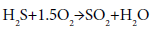 (2)
(2)
The high temperatures and rapid oxygen depletions resulted from combustion are characteristics of the thermal stage. On the catalytic stage, the reaction between the remaining two-thirds of H2S and produced SO2 at lower temperatures is as follows:
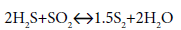 (3)
(3)
Some other reactions such as carbonyl sulfide (COS) and carbon disulfide (CS2) hydrolysis also occur in catalytic convertors [1].
The RF is the first section of the modified Claus process and its operations affect the operation of downstream equipment. Any deficiency in its operation and inappropriate combustion significantly influence combustion products, leading to increasing undesirable components, mainly in form carbonyl sulfide, carbon disulfide and unburned hydrocarbon. COS and CS2 tie up sulfur element in their structure and if they don’t hydrolyze in catalytic stage, remain unconverted. Therefore, these components play a significant role in sulfur emission to the atmosphere via an incinerator. On the other hand, sulfur dioxide emissions to atmosphere are dedicated by increasingly stringent emission control regulations. Any modification in the RF affects sulfur conversion and emissions from Claus plant [7]. One of the main strategies for reducing sulfur emissions is to increase the performance of the Sulfur Recovery Units (Sru) through optimizing operating conditions of the Claus reaction furnace. Optimization of the modified Claus process for further sulfur recovery and lower emissions requires a reliable kinetic model for the RF [9].
The RF of the Claus unit was modeled by equilibrium assumption in several researches. Bennett et al. [10] calculated equilibrium mole percentages of the mixtures of hydrogen sulfide and air for the temperature ranges of 600-2000 K. Khudenko et al. [11] modeled the Claus reaction furnace under oxygen enrichment conditions utilizing Gibbs energy minimization method. Monnery et al. [7] compared the Gibbs energy minimization method, Fisher monograph and western research correlations to model the reaction furnace effluents. They concluded that the results of these various methods were not in agreement with plant data collected after and before the waste heat boiler. Selim et al. [3] computed the optimum operating temperatures of H2S streams containing different components such as CO2 and N2 in the modified Claus process.
Zare Nezhad et al. [12] studied methods of increasing the RF temperature of Claus units. Zarei et al. [6] combined the equilibrium and kinetic approaches in thermal stage modeling. A number of researchers have studied the effects of acid gas feed composition on Claus process experimentally [13-19]. They investigated the sulfur chemistry with acid gas additions in the hydrogen/air [13] and methane/air flames [17,18], and with oxygen [15] , N2 and CO2 additions [19] in the acid gas feed. Gupta et al. [20] reviewed some of the advances in sulfur chemistry in the treatment of acid gases from experimental and design aspects.
Some researchers investigated the modified Claus reaction furnace through detailed kinetic modeling [8,21-24]. In the detailed kinetic modeling, the effluents of reaction furnaces are computed by utilizing reaction schemes consisting of radical, intermediate and molecular reactions.
Pierucci et al. [22] modeled the RF with plug flow assumption (PFR) and considering a detailed kinetic scheme with 130 species and more than 1500 elementary reactions. The detailed kinetic scheme utilized by Manenti et al. [24] consisted of 146 species and 2412 reactions. Their model was a combination of continuous stirred tank (CSTR) and plug flow reactors. In a recent study, Li et al. [25] applied a detailed kinetic modeling of H2S oxidation with the presence of CO2 under rich conditions utilizing the PFR reactor.
Some researchers are interested in developing a kinetic scheme with a limited number of reactions for the RF modeling [26-29]. The first attempt at this field was made by Jones et al. [26] who identified a reaction set to describe the WHB effluents. Javanmardi Nabikandi et al. [27] compared the kinetic and equilibrium approaches to model sulfur recovery unit. Their results show that the kinetic model yields more accurate results than equilibrium model.
Pahlavan et al. [28] simulated a Claus reaction furnace by PROMAX V2.0 simulator. Zarei et al. [29] developed a kinetic scheme to model reaction furnace and validated the model results with the experimental data. The model results were in good agreement with the experimental measured plant data. The mean absolute error of the RF was reported as 7.62%.
Among the mentioned researches, only few studies considered the optimization of the operating conditions of the modified Claus process. Manenti et al. [23] used a kinetic model with 2400 reactions and 140 species in a proper reactor network to optimize elemental sulfur recovery and steam generation. In another work, Manenti et al. [30] conducted an integrated process-energy optimization at the total plant scale. Jones et al. [26] conducted two optimization studies and showed that there existed an optimal steam pressure and H2S/SO2 ratio in the WHB balancing hydrogen yield, oxygen demand, and power generation. Zarei et al. [29] maximized the reaction furnace temperature and optimized the operation of the WHB through maintaining the H2S/SO2 ratio at a constant of two, minimizing COS emission and maximizing sulfur production from the WHB using the developed kinetic scheme.
As previously mentioned, an optimization study requires a suitable kinetic model for Claus reaction furnace, being applied to wider operating conditions and different situations. Previous studies on modeling the RF represented inadequacy of the equilibrium model in predicting the RF effluents [7,27]. In comparison to detailed kinetic studies, kinetic studies with a limited number of reactions estimate the RF and WHB effluents with lower reaction numbers and calculation operation accompanying the acceptable error [26,29]. Among all limited reaction number studies [26,29], the reaction scheme developed by Jones et al. [26] described the WHB effluent. The kinetic model developed by Zarei et al. [29] for Claus reaction furnace provides a good approximation of reactor effluents. It is obtained from experimental data set of single reaction furnace. The research by Zarei et al. [29] was focused on developing a kinetic reaction scheme for specific single furnace by examining different reaction schemes.
However, in the current study, it is attempted to generalize the kinetic reaction network, developed by Zarei et al. [29] for industrial Claus reaction furnaces operated in oil refineries. This work requires further experimental data sets from industrial Claus reaction furnaces operating in oil refineries. The mentioned items are the main differences between the current work and the study by Zarei et al. [29]. A wide plant set obtained from industrial reaction furnaces of operating oil refineries was applied in performing a kinetic model for the RF. The above-mentioned plant data sets include different operating conditions such as different initial concentrations of H2S and CO2, residence times, feed temperatures and pressures. Our analyses showed that at most industrial Claus plants, operations of WHB assumed ideal. In another word, the high quenching rate of WHB did not provide situations for recombination reactions which led to lower sulfur efficiency. It is assumed that the RF and WHB have similar component compositions at different temperature. Therefore, in following work, quenching role of WHB was ignored and only the RF was considered.
Subsequently, a kinetic model to describe experimental data was developed. For this purpose, the reaction scheme introduced in the study by Zarei et al. [29] was used and its kinetic parameters were fitted by applying the data sets of industrial RFs of oil refineries. The adjustment work of the kinetic parameters was conducted by a novel two-step optimization method. The modified kinetic model was validated with experimental plant data. The case studies were performed in which the effects of increasing the air to acid gas flow ratio and feed temperature are investigated in the temperature, sulfur conversion efficiency percentage, H2 and COS molar flow rates of reaction furnace.
The second objective of the current study is to apply the modified kinetic model by optimizing the operating conditions of the Claus reaction furnace of oil refineries. In this study, operating conditions, including reaction furnace temperature and H2S/SO2 ratio at Claus reaction furnace were optimized utilizing the modified kinetic model. A multi-objective function utilized in optimization studies provides solutions without interference of objectivities. The optimization work was conducted by setting the reaction furnace feed temperature and the air to acid gas flow ratio.
Moreover, three correlations are introduced to calculate reaction furnace temperature, sulfur conversion efficiency percentage and the COS conversion percentage. The correlations are obtained by utilizing the modified kinetic model for the Claus reaction furnaces in oil refineries. In developed correlations, effect of air to acid gas flow ratio, residence time, and carbon dioxide to the hydrocarbon content of feed are considered.
Model
Reactor model
Several researchers modeled Claus reaction furnace by considering a single PFR or CSTR reactor, or a combination of CSTR and PFR reactors. Pierucci et al. [22] utilized a single PFR for modeling the RF. Schöneberger et al. [21] proposed a CSTR reactor for computing the RF effluents. Manenti et al. in several works [23,24,31] considered a series of CSTR and PFR reactors for the RF modeling.
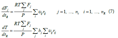
Zarei et al. [29] investigated the effect of considering different reactor networks such as PFR, CSTR and the two combinations of CSTR and PFR in kinetic modeling of the RF and showed that the single PFR reactor is suitable for describing the reaction furnace. In the present study because of cylindrical shape and considering previous works, the reaction furnace was modeled assuming the adiabatic plug flow reactor. Considering adiabatic plug flow assumption and negligible pressure drop, the following ordinary differential equations including mass and energy balance and actual mean residence time equations, should be solved simultaneously [29].
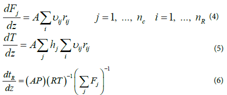
The above equations can be rearranged and the mass and energy balance equations can be written based on residence time as follows:
 (8)
(8)
The above ordinary differential equations were solved using Runge- Kutta order 4. The numerical algorithm was written in MATLAB programming software. Figure 1 shows the solution flow chart of ordinary differential equations.

Figure 1: Solution flow chart of ordinary differential equations.
Kinetic model
Zarei et al. [29] introduced a reaction scheme for describing what actually happens in the reaction furnace. The proposed reaction scheme and their rate expressions are presented in Table 1. Their reaction scheme was obtained by considering experimental data of a single reaction furnace. One feature of the kinetic reaction scheme is thermodynamically consistency of the proposed reactions [29]. In this work, a readjusting work of kinetic parameters of the reaction scheme in Table 1 was done by applying a novel two-step optimization method and utilizing several experimental data of different oil refineries.
| Reaction | Rate Expression | Reference |
|---|---|---|
| H2S↔H2+0.5S2 |  |
[32] |
| CO+0.5S2↔COS | 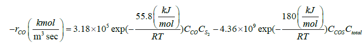 |
[33] |
| CO2+H2↔CO+H2O | 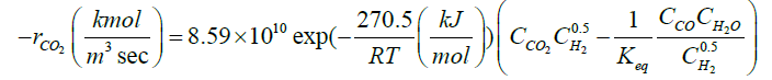 |
[9] |
| CO+H2S ↔COS+H2 | 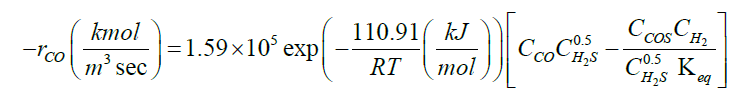 |
[34] |
| H2S+0.5SO2↔H2O+0.75S2 | 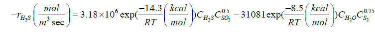 |
[35] |
| CH4+1.5O2→CO+2H2O | 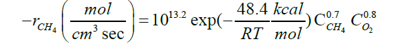 |
[36] |
| H2S+1.5O2→SO2+H2O | 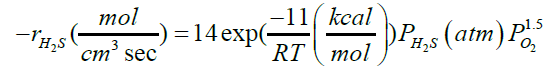 |
[37] |
| NH3→0.5N2+1.5H2 | 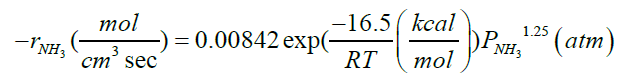 |
[38] |
Table 1: Rate expressions of the chosen kinetic scheme in Zarei et al. [29]
Fitting Parameter Procedure
A modified kinetic model was obtained by adjusting kinetic parameters of the reaction scheme utilizing the experimental plant data-sets of Claus reaction furnaces of oil refineries. In the first step of fitting procedure, an experimental data set is required to adjust tuning parameters and usually is named train data. A test data set must be considered to avoid over fitting. Test data set is not applied in determining unknown parameters and only utilized in evaluating model performance for unfitted data. In the current study, about 70% of the experimental data considered as the train data, and the remaining data (30%) are test data (or validation data). Afterward, a two-step approach was applied to the adjusting work of kinetic parameters. Different order magnitudes of mole percentages for the Claus reaction furnace effluents that cannot be properly depicted in one objective function, is the main reason for considering the two-step approach. Two Objective Function (OB) utilized in the fitting procedure of the two-step approach are as follows:
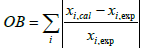 i =H2S, SO2, H2O and H2 (9)
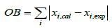 i = CO2, CO and COS (10)
The procedures of adjusting kinetic parameters in the two-step approach are as follows:
1. The Kinetic parameters of reactions relating to H2S, SO2, H2O and H2 components, i.e. hydrogen sulfide decomposition, second Claus reaction and hydrogen sulfide oxidation, were fitted with the experimental oil refineries data and the objective function in accordance with equation 9.
2. After the modification of the adjusted kinetic parameters in the previous step, the kinetic parameters of reactions relating to CO2, CO and COS components, i.e. the COS recombination reaction, reaction between CO and H2S, methane oxidation and water-gas shift reaction, were adjusted with equation 10 for the objective function.
Results and Discussions
The reactions and the adjusted kinetic parameters of the modified kinetic scheme are presented in Table 2. The adjusted kinetic parameters include forward and backward activation energies and rate constants. The modified kinetic model was validated with the reaction furnaces effluents of oil refinery data (test data).
| Reaction | Forward Rate | Backward Rate | |||
|---|---|---|---|---|---|
| k | E | k | E | ||
| H2S↔H2+0.5S2 | 7.64 × 10⁸ | 206.85 | 7.81 × 10⁶ | 132.89 | |
| CO+0.5S2↔COS | 4.80 × 10⁵ | 54.38 | 4.95 × 10⁷ | 152.62 | |
| CO2+H2↔CO+H2O | 4.75 × 10¹⁰ | 279.37 | 5.89 × 10⁸ | 233.59 | |
| CO+H2S ↔COS+H2 | 2.03 × 10⁵ | 132.61 | 3.10 × 10⁶ | 107.76 | |
| H2S+0.5SO2↔H2O+0.75S2 | 2.51 × 10⁶ | 14.62 | 4.28 × 10⁴ | 8.69 | |
| CH4+1.5O2→CO+2H2O | 2.23 × 10¹³ | 46.72 | - | - | |
| H2S+1.5O2→SO2+H2O | 14.85 | 10.65 | - | - | |
Table 2: The reactions and adjusted kinetic parameters of modified kinetic scheme.
Table 3 shows the Mean Absolute Percentage Errors (MAPE) for H2S, SO2, H2 and H2O components for oil refinery data used in optimizing (train data) and validating (train data) of the modified kinetic model. Based on Table 3 for H2S, SO2, H2 and H2O components, maximum MAPEs for both train and test data set with values 5.905% and 7.981%, respectively belong to H2.
| Components | Train | Test |
|---|---|---|
| H2S | 3.039 | 6.719 |
| SO2 | 2.285 | 5.739 |
| H2O | 4.665 | 4.739 |
| H2 | 5.905 | 7.981 |
Table 3: The MAPEs for H2S, SO2, H2O and H2 components for train and test data sets.
Coefficients of determinations for CO2, CO and COS are 0.9989, 0.9805 and 0.9873, respectively. Use of the coefficient of determination for CO2, CO and COS is due to their low concentrations in the Claus reaction furnace effluents. Figures 2-8 compare the calculated mole percentages of the reaction furnace effluents with experimental data for both train and test data-sets. According to Figures 2-5 and Table 3 for H2S, SO2, H2O and H2, a good agreement is seen between experimental and calculated mole percentages for both test and train data set. Figures 6-8 and the mentioned coefficient of determinations show the goodness of fit for CO2, CO and COS compounds. A good agreement between the calculated mole percentage from the modified kinetic scheme and experimental mole percentages in Figures 6-8 ensure its precision in different situations and operating conditions.

Figure 2: Calculated H2S mole percent from the modified kinetic model in comparison to experimental data for both train and test data sets.

Figure 3: Calculated SO2 mole percent from the modified kinetic model in comparison to experimental data for both train and test data sets.

Figure 4: Calculated H2O mole percent from the modified kinetic model in comparison to experimental data for both train and test data sets.

Figure 5: Calculated H2 mole percent from the modified kinetic model in comparison to experimental data for both train and test data sets.

Figure 6: Calculated CO2 mole percent from the modified kinetic model in comparison to experimental data for both train and test data sets.

Figure 7: Calculated CO mole percent from the modified kinetic model in comparison to experimental data for both train and test data sets.

Figure 8: Calculated COS mole percent from the modified kinetic model in comparison to experimental data for both train and test data sets.
Case studies
Effect of air to acid gas flow ratio: In the following section, the effect of increasing the air to acid gas flow ratio on the sulfur conversion efficiency percentage, H2 and COS molar flow rates from the reaction furnace effluent and the reaction furnace temperature is studied. Based on the initial air to acid gas flow ratio, the limits 1.5-3 for the air to acid gas flow ratio were chosen. It must be ensured that the whole oxygen combusts at the reaction furnace and no unburned oxygen percolates to downstream waste heat boiler and catalytic stages, to remains unconverted. Oxygen breakthrough is a serious problem for the sulfur catalyst resulting in a deactivation by a mechanism thought to be sulphation. Figure 9 shows the effect of increasing the air to acid gas flow ratio on the reaction furnace temperature and the sulfur conversion efficiency percentage.

Figure 9: Effect of increasing air to acid gas flow ratio on sulfur conversion efficiency percentage and reaction furnace temperature (K).
According to Figure 9, increasing the air- to- acid -flow ratio generally results in riser reaction furnace temperature and lower sulfur conversion efficiency percentage. These outcomes can be discussed with higher oxygen available for combustion of hydrogen sulfide and other impurities such as ammonia and hydrocarbons. The combustion of hydrogen sulfide and other impurities are exothermic reactions liberating heat that result in higher reaction furnace temperature. Incremental reaction furnace temperature due to higher air to acid gas flow ratio prepares situations for the decomposition reactions. According to Figure 9, conversion efficiency percentages of sulfur increases, because of the higher conversion of hydrogen sulfide as the result of higher reaction furnace temperature, which is suitable for hydrogen sulfide decomposition reaction and, subsequently, more sulfur and hydrogen production. Gradually decrement of sulfur conversion efficiency percentages can be interpreted with higher conversion of hydrogen sulfide as the result of more oxygen consumption. Therefore, hydrogen sulfide with decomposition capability, instead of decomposition reaction, combusts, and SO2 is produced. Consequently, lower sulfur and hydrogen is composed.
As more hydrogen sulfide is consumed in the combustion reaction than decomposition reaction, hydrogen content is decreased. The effects of increasing air to acid gas flow ratio on the H2 and COS molar flow rates are presented in Figure 10. As the figure shows, the H2 molar flow rate first raises with the air to acid gas flow ratio increment. Afterward, its quantity decreases. The observed H2 trend with the air to acid gas flow ratio justifies the above mentioned statements about lower hydrogen sulfide decomposition reaction. Figure 10 shows decreasing trend of COS as a function of the air to acid gas ratio. At higher temperature situations, the COS decomposition reaction takes place and lower COS is maintained in the system.

Figure 10: Effect of increasing air to acid gas flow ratio on H2 and COS molar flow rate (mol/sec).
Effect of reaction furnace feed temperature: In addition to air to acid gas flow ratio, reaction furnace temperature is one of the important operating variables influencing operating conditions of the reaction furnace. In this section, the effects of reaction furnace feed temperature are investigated in the reaction furnace temperature, sulfur conversion efficiency percentage, COS and H2 molar flow rates from reaction furnace effluent and are depicted in Figures 11 and 12.

Figure 11: Effect of increasing feed temperature (K) on sulfur conversion efficiency percent and reaction furnace temperature (K).

Figure 12: Effect of increasing feed temperature (K) on H2 and COS molar flow rate (mol/sec).
The reaction furnace temperature ranges from 300-500 K. Figure 11 shows the increase in the reaction furnace temperature results in higher reaction furnace temperature due to higher enthalpy of inlet material. A 150 degree increase in reaction furnace temperature is observed because of rising feed temperature from 300 to 500 K. Incremental reaction furnace temperatures promotes hydrogen sulfide decomposition reaction. Because of more hydrogen sulfide decomposition reaction, the amount of sulfur and hydrogen are raised. Incremental conversion efficiency percentage of sulfur is explained by higher decomposition reaction due to higher resultant reaction furnace temperature. A 200 degree increment of reaction furnace temperature increase sulfur efficiency percentage (3.86%) which is unusable.
Effects of increasing reaction furnace temperature on molar flow rates of H2 and COS are demonstrated in Figure 11. According to Figure 11, molar flow rates of H2 and COS at the reaction furnace outlet have negligible increments with the reaction furnace feed temperature. At high temperature of the reaction furnace, decomposition reactions are favorable; the higher amount of the hydrogen sulfide decomposes and higher amount of hydrogen produces. The above statement confirms the observed trend of hydrogen molar flow rate along with the increase in the reaction furnace feed temperature [32,33].
Experimental studies conducted by Karan et al. [34] showed that following reaction between CO and H2S is favorable at high temperature situations faced in the Claus reaction furnace:
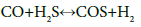 (11)
(11)
The increasing feed temperature and the resulting raised reaction furnace temperature lead to higher quantity of decomposition reaction and reaction in accordance with equation 9. Decomposition reaction and reaction 11 proceed in such a way that reaction 11 for COS production overtakes COS consumption reaction, i.e. COS decomposition reaction, and result in production of higher quantity of COS. A comparison between Figures 9 and 11 demonstrates that the air to acid gas ratio has a more considerable effect on the operating conditions of the Claus reaction furnace.
Modification of correlations
Paskall et al. [1] proposed a set of correlation for calculating CO, H2, COS, CS2 and S at the reaction furnace outlet. In their correlations, mole composition of inlet flow was a variable, but the effect of reactor residence time wasn’t considered. It is the main reason of deficiency of correlations in predicting reactor outlet [7]. Agreement between experimental data and model prediction encouraged to develop a set of correlations for reaction furnace temperature at the outlet, sulfur conversion efficiency percentage and COS conversion percentage. The sulfur conversion efficiency percentage and reaction furnace temperature are utilized in evaluating reaction furnace and overall process performances.
The concentration of COS determines the performance of the reactor in impurity destruction. These correlations make simple performance evaluations without requiring to run the kinetic model. In order to modify the correlations, air to acid gas flow ratio was changed and model predictions were correlated. The correlations for reaction furnace temperature and sulfur conversion efficiency percentage are as follows:
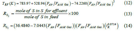
The mean absolute percentage errors for reaction furnace temperature and the sulfur conversion efficiency percentage are 1.83% and 4.66%.
Based on the mole of carbon dioxide to mole of carbon in hydrocarbons in the feed (x), were set two correlations for COS conversion percentages (RCOS). Definitions of x and RCOS are as follows:
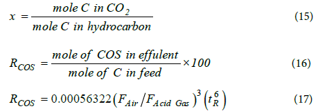
The mean absolute percentage errors of the correlations are 15.54% and 16.52%, respectively.
Optimization
In this study, operation conditions of the industrial reaction furnaces of the Claus sulfur recovery unit were optimized. In this regard, the reaction furnace temperature is maximized and the H2S to SO2 ratio at the reaction furnace effluents was maintained at optimal value 2 to maximize hydrogen sulfide conversion [12].
Operating variables that can be adjusted in order to maintain the H2S/SO2 ratio in the Claus reaction furnace at constant two and maximize reaction furnace are the reaction furnace feed temperature and the ratio of air to acid gas flow. The variation ranges of adjusting operating variables are chosen as follows:
1. 1.5-3 for the ratio of air to acid gas flow based on initial air to acid gas ratio.
2. 150°C-300°C for the reaction furnace feed temperature.
The gamultiobj code of MATLAB programming software was used in optimization work. In former single objective function methods, such as utility theory, weighted sum method, etc., determination of a single objective function is possible. However, the problem lies in the proper selection of the weights or utility functions [39]. Scaling amongst objectives is needed and small perturbations in the weights can sometimes lead to quite different solutions [39]. Therefore, an optimization method would return a single solution rather than a set of solutions that can be examined for trade-offs. For this reason, a set of solutions considering the multiple objectives is preferred [39]. A multiobjective problem investigates a set of solutions, which satisfies the objectivities at an acceptable level without being dominated problem by any other solutions [39].
The optimal operating conditions leading to maximum reaction furnace temperature while maintaining H2S to SO2 ratio at constant two are listed in Table 4. The reaction furnace temperature and absolute difference of H2S to SO2 ratio from constant 2 before and after optimization work are presented in Table 5. As can be seen in Table 5, the reaction furnace temperature is maximized and the ratios of H2S to SO2 are close to constant two. The energy required for increasing feed temperature can provide inside the thermal stage from the steam produced in the WHB.
| Reaction Furnace | Feed Temperature (K) | Air to Acid Gas Ratio |
|---|---|---|
| 1 | 567.87 | 2.3551 |
| 2 | 578.19 | 2.6938 |
| 3 | 534.50 | 2.4317 |
Table 4: Adjusted operating parameters of optimized Claus reaction furnaces in oil refineries.
| Reaction Furnace | Before Optimization | After Optimization | ||
|---|---|---|---|---|
| abs (H2S/SO2-2) | TRF (K) | abs (H2S/SO2-2) | TRF (K) | |
| 1 | 0.15745 | 1553.1 | 0.0052812 | 1764.9 |
| 2 | 0.11778 | 1544.7 | 0.041752 | 1770.5 |
| 3 | 0.030745 | 1603.9 | 1.38E-07 | 1750.7 |
Table 5: Values of objective functions before and after optimization.
Conclusion
In this study, a modified kinetic scheme was performed for the description of the Claus reaction furnace of oil refineries. The modified kinetic scheme can be applied in wider operating conditions and different situation such as: initial concentration, feed temperature and pressure. The modified kinetic scheme is developed by a novel two-step optimization method. According to the calculated mole percentages from the modified kinetic model and experimental data set of plants, H2 component has the maximum mean percentage errors in accordance with 5.905 and 7.981% for the train and test data sets. Coefficients of determinations (R) for CO2, CO and COS are 0.9989, 0.9805 and 0.9873, respectively. A good match is observed between the results of the kinetic model with the experimental reaction furnace. Validation of the modified kinetic model with test data sets shows the admissibility and precision of the model in wide operating conditions.
Air to acid gas flow ratio and the reaction furnace feed temperature are two operating variables of the Claus reaction furnace that influence the operating conditions of Claus reaction furnace. The author investigated the changes of temperature, sulfur conversion efficiency percentages, H2 and COS molar flow rates of Claus reaction furnace along with the above mentioned operating variable. It is concluded that both reaction furnace feed temperature and air to acid gas flow ratio have an increasing effect on the reaction furnace temperature. A comparison between the results of air to acid gas flow ratio and reaction furnace feed temperature showed that the air to acid gas ratio have more notable effects on the operating conditions of the Claus reaction furnace.
Three correlations were introduced for calculating reaction furnace temperature, sulfur conversion efficiency percentage and COS conversion percentage. Air to acid gas ratio, residence time, and mole of carbon dioxide to mole of carbon in hydrocarbons were considered in the correlations.
An optimization study was conducted to investigate the optimum operating condition of the reaction furnace including maximum reaction furnace operating temperature and maintaining the H2S/SO2 ratio at a constant of two. The reaction furnace feed temperature and air to acid gas flow ratio parameters were optimized using a multiobjective optimization method.
Nomenclature
A: Cross-sectional area (m2)
C: Concentration (mol/m3, kmol/m3, mol/cm3)
E: Activation Energy (J/mol or Cal/mol)
F: Molar Flow (mol/sec)
h: Enthalpy (J/mol)
k: rate constant (mol/m3sec, kmol/m3sec, mol/cm3sec)
nC: Number of components
nR: Number of reactions
P: Pressure (Pa)
r: rate (mol-sec-m)
R: Gas constant (8.314 J/mol K, 1.987 Cal/mol K)
Rk: Conversion of component k
tR: Actual mean residence time(sec)
T: Temperature (K)
 : Stoichiometric coefficient of component j in reaction i Subscripts
i: Reaction number
j: Component number
References
- Paskall HG, Sames JA (1998) Sulphur recovery, Western Research, Canada.
- Sehgal V (2009) Technical and economic comparison of natural gas sweetening process, Dalhousie University Canada.
- Selim H, Gupta AK, Sassi M (2008) Acid gas composition effects on the optimum temperature in claus reactor. 6th International Energy Conversion Engineering Conference (IECEC).
- Cover AE, Hubbard DA, Jain SK, Shah KV, Koneru PB, et al. (1985) Review of selected sulfur recovery processes for sng production, Final Report.
- Bassani A, Pirola C, Maggio E, Pettinau A, Frau C, et al. (2016) Acid gas to syngas (ag2sâ„¢) technology applied to solid fuel gasification: Cutting h2s and co2 emissions by improving syngas production. Appl Ener 184: 1284-1291.
- Zarei S, Ganji H, Sadi M, Rashidzadeh M (2016) Thermo-kinetic modeling and optimization of the sulfur recovery unit thermal stage. Appl Therm Eng 103: 1095-1104.
- Monnery WD, Svrcek WY, Behie LA (1993) Modelling the modified claus process reaction furnace and the implications on plant design and recovery. Can J Chem Eng 71:Â 711-724.
- Manenti G, Papasidero D, Manenti F, Bozzano G, Pierucci S (2012) Design of sru thermal reactor and waste heat boiler considering recombination reactions. Procedia Eng 42: 414-421.
- Karan K (1998) An experimental and modeling study of homogeneous gas phase reactions occurring in the modified claus process.
- Bennett HA, Meisen A (1973) Hydrogen sulphide - air equilibria under claus furnace conditions. Can J Chem Eng 51: 720-724.
- Khudenko BM, Gitman GM, Wechsler TEP (1993) Oxygen based claus process for recovery of sulfur from gases. J Environ Eng 119: 1233-1251.
- Zarenezhad B, Hosseinpour N (2008) Evaluation of different alternatives for increasing the reaction furnace temperature of claus sru by chemical equilibrium calculations. Appl Therm Eng 28: 738-744.
- Selim H, Ibrahim S, Al Shoaibi A, Gupta AK (2014) Investigation of sulfur chemistry with acid gas addition in hydrogen/air flames. Appl Ener 113: 1134-1140.
- Ibrahim S, Al Shoaibi A, Gupta AK (2014) Toluene destruction in thermal stage of claus reactor with oxygen enriched air. Appl Ener 115: 1-8.
- Selim H, Ibrahim S, Al Shoaibi A, Gupta AK (2013) Effect of oxygen enrichment on acid gas combustion in hydrogen/air flames under claus conditions. Appl Ener 109: 119-124.
- Ibrahim S, Al Shoaibi A, Gupta AK (2013) Role of toluene in hydrogen sulfide combustion under claus condition. Appl Ener 112: 60-66.
- Selim H, Al Shoaibi A, Gupta AK (2011) Effect of h2s in methane/air flames on sulfur chemistry and products speciation. Appl Ener 88: 2593-2600.
- Selim H, Al Shoaibi A, Gupta AK (2012) Fate of sulfur with h2s injection in methane/air flames. Appl Ener 92: 8.
- Selim H, Gupta AK, Al Shoaibi A (2012) Effect of co2 and n2 concentration in acid gas stream on h2s combustion. Appl Ener 98: 53-58.
- Gupta AK, Ibrahim S, Al Shoaibi A (2016) Advances in sulfur chemistry for treatment of acid gases. Progress in Energy and Combustion Science 54: 65-92.
- Schöneberger J, Arellano-Garcia H, Thielert H, Wozny G (2007) An efficient approach to robust simulation of claus processes in coking plants. Computer Aided Chemical Engineering 24: 521-526.
- Pierucci S, Ranzi E, Molinari L (2004) Modeling a claus process reaction furnace via a radical kinetic scheme. Computer Aided Chemical Engineering 18: 463-468.
- Manenti F, Papasidero D, Bozzano G, Pierucci S, Ranzi E, et al. (2013) Total plant integrated optimization of sulfur recovery and steam generation for claus processes using detailed kinetic schemes. Computer Aided Chemical Engineering 32: 811-816.
- Manenti F, Papasidero D, Frassoldati A, Bozzano G, Pierucci S, et al. (2013) Multi-scale modeling of claus thermal furnace and waste heat boiler using detailed kinetics, Computers & Chemical Engineering 59: 219-225.
- Li Y, Yu X, Li H, Guo Q, Dai Z, et al. (2017) Detailed kinetic modelling of h2s oxidation with presence of co2 under rich condition. Appl Ener 190: 824-834.
- Jones D, Bhattacharyya D, Turton R, Zitney SE (2012) Rigorous kinetic modeling and optimization study of a modified claus unit for an integrated gasification combined cycle (igcc) power plant with co2 capture. Ind Eng Chem Res 51: 2362- 2375.
- Javanmardi N, Fatemi S (2015) Kinetic modelling of a commercial sulfur recovery unit based on claus straight through process: Comparison with equilibrium model. J Ind Eng Chem 30: 50-63.
- Pahlavan M, Fanaei MA (2015) Modeling and simulation of claus unit reaction furnace. Iran J Oil Gas Sci Technol 5: 42-52.
- Zarei S, Ganji H, Sadi M, Rashidzadeh M (2016) Kinetic modeling and optimization of claus reaction furnace. J Nat Gas Sci Eng 31: 747-757.
- Manenti F, Papasidero D, Bozzano G, Ranzi E (2014) Model-based optimization of sulfur recovery units. Comput Chem Eng 66: 244-251.
- Manenti F, Papasidero D, Cuoci A, Frassoldati A, Faravelli T, et al. (2012) Reactor network analysis of claus furnace with detailed kinetics. Comput Aided Chem Eng 30: 1007-1012.
- Dowling NI, Hyne JB, Brown DM (1990) Kinetics of the reaction between hydrogen and sulfur under high-temperature claus furnace conditions. Ind Eng Chem Res 29: 2327-2332.
- Karan K, Mehrotra AK, Behie LA (1998) Cos-forming reaction between co and sulfur: A high temperature intrinsic kinetics study. Ind Eng Chem Res 37: 4609-4616.
- Karan K, Mehrotra AK, Behie LA (1999) A high-temperature experimental and modeling study of homogeneous gas-phase cos reactions applied to claus plants. Chem Eng Sci 54: 2999-3006.
- Tesner P, Nemirovskii M, Motyl D (1990) Kinetics of the thermal decomposition of hydrogen sulfide at 600-1200°c. Kinetics and catalysis 31: 1081-1083.
- Dryer FL, Glassman I (1973) High-temperature oxidation of CO and CH4. Symposium (International) on Combustion 14: 987-1003.
- Monnery WD, Hawboldt KA, Pollock A, Svrcek WY (2000) New experimental data and kinetic rate expression for the claus reaction. Chem Eng Sci 55: 5141-5148.
- Monnery WD, Hawboldt KA, Pollock AE, Svrcek WY (2001) Ammonia pyrolysis and oxidation in the claus furnace. Ind Eng Chem Res 40: 144-151.
- Konak, Coit DW, Smith AE (2006) Multi-objective optimization using genetic algorithms: A tutorial. Reliab Eng Syst Saf 91: 992-1007.
Citation: Zarei S (2018) A Modified Kinetic Reaction Scheme for Claus Reaction Furnaces in Oil Refineries. Innov Ener Res 7: 215. DOI: 10.4172/2576-1463.1000215
Copyright: © 2018 Zarei S. This is an open-access article distributed under the terms of the Creative Commons Attribution License, which permits unrestricted use, distribution, and reproduction in any medium, provided the original author and source are credited.
Select your language of interest to view the total content in your interested language
Share This Article
Recommended Journals
Open Access Journals
Article Tools
Article Usage
- Total views: 5203
- [From(publication date): 0-2018 - Dec 01, 2025]
- Breakdown by view type
- HTML page views: 4251
- PDF downloads: 952