A Systematic Review of Energy Harvesting from Roadways by using Piezoelectric Materials Technology
Received: 22-Feb-2018 / Accepted Date: 05-Mar-2018 / Published Date: 09-Mar-2018 DOI: 10.4172/2576-1463.1000191
Abstract
Piezoelectric energy harvesting technology is attracting more attention in recent years due to the trend of finding new and green sources of energy. This project presents a state of the art review in the area of using piezoelectric materials to harvest energy from roadways. The aim of this project is to investigate the process of harvesting energy from roadways starting from the used piezoelectric materials, harvesters and the conditions of the roadways. Many papers were evaluated and analyzed to study the current progress in the area including of the efficiency and feasibility of extant work. The results were obtained from various sources under different circumstances and compared, in order to determine the most efficient outcome in terms of cost and implementation in practical applications.
Keywords: Piezoelectric energy harvesting; Piezoelectric materials; Roadways
Introduction
Since the world has been facing a lot of issues in terms of using conventional energy to generate electricity, many countries have found it essential to seek alternative, environmentally friendly, low-cost energy resources to produce energy. There are many natural resources which can be used to produce the energy such as heat, sunlight, wind, vibration, and stress or movement [1-4]. These resources can be collected and converted into electrical energy. In order to do convert these resources into electrical energy, energy harvesting processes must be used [5].
Based on the work of [6-10], the word- “piezo” comes from Greek which means the act of pressing, and- “piezoelectric”, as the term indicates, means materials that have the piezoelectric effect. This section presents a journey through the history of piezoelectricity and its development over the years. The first indication that pressure may generate electricity was introduced by Coulomb in 1815. After five years, according to Hauy and Becquerel, friction or contact electricity is the main cause of the charges that are produced from compression. Moreover, stretching rubber result charges that may have the same outcome as the use of crystalline minerals. In 1880, the piezoelectric phenomenon was found by Pierre and Jacques. Piezoelectric was first applied in a major application by Langevin and his co-workers in 1917. Their application was a piezoelectric transducer to locate submarines and determine their depth during World War I. this application used quartz sandwiched between two metal plates which later started the development of the sonar. Between 1920 and 1940, there were many applications that used single crystals. In addition, fluids and solids had nondestructive tests, quartz resonators and transient pressure measuring methods. During that period, many examples of natural crystals were discovered such as Rochelle salt, tourmaline, sodium potassium tartrate and quartz. Between 1940 and 1965, because of World War II, the piezo-ceramics had to be developed in terms of the sensitivity and the resulting power. Oscillators and filters were examples of using piezoelectric in electronics. Moreover, the demand for enhanced piezoelectric materials caused a rapid growth in synthetic materials which led to new and improved piezoelectric properties. Furthermore, certain properties were needed which started the process of doping with metallic impurities to achieve these qualities, for instance, ease of poling, piezoelectric coupling coefficient, dielectric constant and stiffness. Another example is the Lead-Zirconate-Titanate Pb (Zr,TiO3) alloy which was introduced due to the advances in the Barium Titanate (BaTiO3); also, a full understanding of the perovskite crystal structure with electromechanical activity. Circuit elements, small microphones, signal filter elements, ceramic audio tone transducers, ignition systems, relays, and enhanced sonar systems are some of the areas that had many improvements or boost or breakthrough due to the advances in piezoelectric materials. Japan had a vast commercial success in terms of the piezoelectric materials and devices in the period between 1965 and 1980. During these years, removing the restraints of rigid nature of ceramics resulted in the improvement of polyvinylidene fluoride (PVDF). From 1980 until the present, the majority of the work has been concentrated on low power applications, increasing the reliability and solid state motion.
Working Principle
Piezoelectric materials are crystals that have the ability to produce electricity in case of compression or vibration and the basic principle of piezoelectricity is shown in Figure 1. An external force, pressure or a strain applied on crystalline materials which result in an electrical voltage.

Figure 1: Working principle.
A typical non-centrosymmetric crystal structure such as a perovskite (lead zirconate titanate) is shown in Figure 2. When the unit cell is above the Curie temperature (Tc) or Cubie point, which is the temperature that changes some materials in terms of reforming or losing their permanent magnetic properties. It has a symmetric cubic state as shown in Figure 2 [11]. On the other hand, when the unit cell is below the Cubie temperature, it is transformed into an asymmetric tetragonal structure as shown in Figure 2 [12]. Each unit cell in this crystal has a net non-zero charge. Therefore, the unit cell is turning into an electric dipole. The numbers of electric dipoles inside piezoelectric materials have a significant effect on the structure of these materials. Electric dipoles are induced in two ways: specific molecular groups with various electrical features or by materials such as Barium titanate (BaTiO3) and PZTs (lead zirconate titanate) which have ion lattice sites with asymmetric charge surroundings. A dipole is a vector (P) which means it has a value and a certain direction depending on the electrical charges. These dipoles shape areas that are called Weiss domains because they usually go in the same direction if they are side by side. The Weiss domains are in every direction; however, these domains can be adjusted to have the same direction by polling, which is the process of applying an external electric field on the material. When an electric filed is applied on these domains, the boundaries of the domains shift, which increase the strength of domains that have the same direction as the electric field. As the electric field increases, the polling will last until all the domains have the same direction of the electric field according to [13]. Figure 3 shows the different states of the Weiss domains based on the level of the applied electric field.

Figure 2: Perovskite structure of PZT.

Figure 3: Different states of the Weiss domains under the effect of an electric field a) before, (b) during (c) after poling process.
In conclusion, the voltage is induced in piezoelectric materials due to the fact that the crystalline structure is disturbed when a pressure or stress is applied which results in a new direction for the polarization of the electric dipoles. Based on the way that dipoles were induced, either molecular groups or ions, the new polarization has two main reasons: re-orientation of the molecular groups or reform of the ions inside the crystalline structure. As a result, generating more electricity requires more mechanical pressure and more change in the polarization.
Types of Effects
The closed hydronic circuit of the solar PV/T hybrid collector was firstly injected with the Nanofluid, and a static pressure of 0.4 bar and flow rate of 3.25 L/min was maintained. Figure 4 shows a photographic view of Nanofluid insertion process. The experimental tests took place in March 2017, solar irradiation, wind speed, inlet, outlet, and ambient temperatures were all recorded on hourly basis starting from 9:00 AM till 15:00 PM. The experiments have been repeatedly conducted so to obtain nearly matching or fixed surrounding atmospheric conditions and hence the comparison analysis becomes as realistic and accurate as possible. Selected two days data representing each different heat carrier fluid scenario were used for the analysis. The following Figure 5 compares solar irradiation, wind speed, and ambient temperatures for the two days of interest climatic conditions.

Figure 4: Direct piezoelectric effect.

Figure 5: Reverse piezoelectric effect.
Methods
The piezoelectric effect considers crystalline materials in terms of a linear electromechanical interaction between the mechanical and electrical state. This effect is a reversible process which results in two types of effect: the direct piezoelectric effect which is an applied mechanical force causing an internal generation of electrical charge as shown in Figure 4. And, the reverse piezoelectric effect which is an applied electrical field causing an internal generation of mechanical strain as shown in Figure 5. Lead zirconate titanate crystals are a good example of these effects. When the static structure of these crystals is deformed by 0.1% of their original dimension, they will produce enough piezoelectricity. On the other hand, when an external electric field is applied on the same crystals, their static dimension will change by 0.1% [14]. According to the work done by Kim SG, Priya S & Kanno [13], the two types of effect are determined and influenced by many coefficients and parameters as follows:
 (1)
(1)
 (2)
(2)
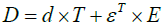
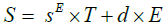
Where D is the electric flux density, T is the mechanical stress, ɛT is Permittivity (for T = constant) and E is the electric field in the first equation. Where, in the second equation, E is the mechanical strain, the compliance or elasticity coefficient (for E = constant) is E and d is the piezoelectric charge coefficient.
Piezoelectric materials have three main types: natural piezoelectric substrates, piezoelectric ceramics and Polymer-film piezoelectric. The first are natural crystals that are found at the surface or deep within the earth such as quartz (SiO2). Quartz is considered the most common natural piezoelectric material because it has a strong piezoelectricity due to its crystalline structure, meaning that when pressure is applied on a quartz crystal an electrical polarization can be observed along the pressure direction. Another example is tourmaline, which is usually black but may vary from violet to green and pink. In addition, amazonite and sodium potassium tartrate, also known as Rochelle salt. The second type is the piezoelectric ceramics; for example, Lead Zirconate Titanate (Pb[ZrxTi1-x]O3) also known as PZT which is the most economical and used piezoelectric element. Moreover, gallium orthophosphate (GaPO4) has the same characteristics as quartz due to the similarity in their crystalline structure. On the other hand, the piezoelectric effect of gallium orthophosphate has double the piezoelectric effect of the quartz. This difference results in more use of gallium orthophosphate in mechanical applications. In addition, Barium Titanate (BaTiO3) which is an electrical ceramics used for microphones and transducers, is usually replaced by lead zirconate titanate (PZT) for piezoelectricity; also, Berlinite (AlPO4), Zinc oxide (ZnO), Aluminum Nitride (AiN) and Lead Titanate. The third category is the Polymer-film piezoelectric, such as Polyvinylidene Fluoride (PVDF). This type is not commonly used in practical applications [15].
Based on the work done by [16], many design parameters that determine the efficiency of any material have been tested in different publications: Thickness, more energy is produced when a thin material is used. Structure, bimorph structure has twice the output of a unimorph structure. Loading mode, increase in mass or force produces more energy. Geometry, tapered form generates more energy than any other shape. Electrical connection has two cases: parallel when current source is used, and series with a voltage source. Material type as PZT, PVFD, Quick-Pack, and PVFD which indicates that the material with high quality factor (Q-factor) produces more energy Fixation, external force results in more energy than fixed at two ends due to the deflection that caused by a fixation at one end. Load impedance must be the same as the piezoelectric impedance at the operating frequency. Resonance frequency needs to be equal to the fundamental vibration frequency.
Energy Harvesting
The basic and general definition of energy harvesting is the process of scavenging energy from any physical phenomenon in the surrounding environment and converting it into usable electric power. Energy harvesting has high potential for the low voltage and low power applications such as transportation, medical equipment, consumer devices and industrial controls. In addition, the applications that need a backup battery such as using a battery in a remote location. The energy harvesting process has multiple stages in order to produce high and efficient amount of electricity as shown schematically in Figure 6 [17].

Figure 6: Energy harvesting stages.
Before the first stage, energy can be obtained from different sources such as thermal, solar and wind but the main focus of this project is the mechanical energy caused by stress, strain and vibration. The first stage includes different types of materials, devices and sensors that have the ability to convert the input energy to electrical voltage. Examples of these energy generators are piezoelectric (PZT) crystals, fiber composites, solar photo voltaic cells and thermoelectric generators (TEGs). These generators produce an alternating current (AC) to the next stage which is the detector. The detector uses an AC to direct current (DC) converter in order to start the storage process. Furthermore, the acceptable level of voltage and the current in the detector, vary between 0V to 500V and 200nA to 400mA, respectively. Moreover, the amount of power generated in this step is measured in micro watt (uW). As the energy transferred form the energy generators to the detectors, the resulting electrical signals have to be collected and stored by an energy storage device such as a capacitor. The mechanism of the storage process starts with defining upper and lower limits of the voltage ± V low DC (VL) and ± V high DC (VH). These limits are based on the minimum VL and the maximum VH voltage that are required by the load. When the output voltage level reaches VH, the switch, which is a diode, is turned on and the power is injected to the load. However, when the voltage level decreases and reaches VL, the switch is turned off and the process cycle starts again until the VH is achieved.
Scales of energy harvesting
As explained previously, energy harvesting there are two types of energy harvesting which vary in terms of scale and the output. The first type is macro energy harvesting, which is used to feed the electric grid in a large scale. This type includes energy harvesting coming from the sun and the wind. The second type is the micro energy harvesting, which has a very low output compared to macro harvesting, and is used primarily in portable and remotely located devices. This type of harvesting is the main concern in this project as is shown in the next section.
Piezoelectric micro-electromechanical system
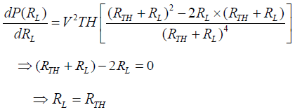
Figure 7 shows the energy flow in a piezoelectric energy harvester in a block scheme. The first phase represents the conversion of the energy produced by the available source into cyclic oscillation using a mechanical assembly. In this phase, some mechanical energy is lost for several reasons such as unmatched mechanical impedance, damping factor, which is the ratio of the source impedance to the load impedance, and backward reflection. Damping factor is the ratio of the source impedance to the load impedance. The second phase is responsible of converting the cyclic oscillations into electrical energy by the piezoelectric effect. This phase has some losses, such as electromechanical losses of the piezoelectric material, and these losses are based on three factors. In the first phase, the electromechanical coupling factor (k) which measures the efficiency of the conversion process between the mechanical to electrical energy. In the second phase, d represents the product of piezoelectric stress coefficient and g is the piezoelectric voltage coefficient. In the third phase, the output electrical energy has to be converted through a dc/dc converter which results in electrical loss due to unmatched electrical impedance. Unmatched impedance either mechanical or electrical has a major impact on the efficiency of the process and is related to the maximum power transfer theorem which states that the impedance of the source has to be equal to the load impedance in order to achieve the maximum output power [18]. The proof of this theory is shown below, and is obtained from a Thevenin’s equivalent circuit is shown in Figure 8 that has a voltage source (VTH), source impedance (RTH), load impedance (RL) and load current (IL).

Figure 7: Piezoelectric micro-electromechanical system (MEMS).

Figure 8: Equivalent Thevenin circuit.
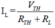
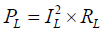
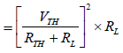
Where PL is the power absorbed by the load.
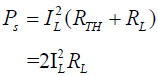
Where PS is the power injected by the source
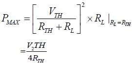
Therefore,
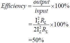
This percentage means that half of the generated power is delivered to the load side.
Comparison of recent small-scale piezoelectric energy harvesters
Table 1 [19-32] shows the differences in the performance of various energy harvesters between many sources. These differences are based on multiple parameters such the material used, area, volume, acceleration, resonant frequency, harvested power and power density.
| Reference | Active material | Active area, mm2 | Active volume mm3 | Acceleration, g | Frequency, H2 | Power, uW | Power density, uW/mm3 |
|---|---|---|---|---|---|---|---|
| [19] | PZT,d11 | 0.96 | 0.48 | 2 | 870 | 1.4 | 7.78 |
| [20] | PZT,d11 | 92.5 | 0.26 | 0.5 | 126 | 5.3 | 20.5 |
| [21] | PZT,d11 | 120 | 0.02 | 4 | 1300 | 22 | 1100 |
| [22] | PZT | 9.45 | 1.89 | 0.2 | 76 | 13.9 | 7.35 |
| [23] | AIN,d11 | 3.573 (est.) | 2.8 | 0.275 | 214 | 0.63 | 0.23 |
| [24] | AIN,d11 | 1.573 (est.) | - | 0.126 | 214 | 0.55 | - |
| [25] | AIN | - | 1.63 | 1 | 857 | 0.18 | 0.11 |
| [26] | AIN | - | 15 | 0.2 | 599 | 69 | 4.6 |
| [27] | PZT | - | 20.9 | 1 | 329 | 7.35 | 0.35 |
| [28] | PZT | - | 18.6 | 1 | 235 | 14 | 0.75 |
| [29] | PZT,d11 | 1.8 | 1.05 | 0.39 | 528 | 1.1 | 1.05 |
| [30] | PZT,d11 | 2.65 | 0.78 | 1 | 608 | 2.16 | 2.77 |
| [31] | PZT,d11 | 49 | 27 | 1.5 | 154 | 205 | 7.59 |
| [32] | KNN,d11 | 56.1 | 0.168 | 1 | 1036 | 1.1 | 6.54 |
Table 1: Comparison of recent small-scale piezoelectric energy harvesters.
Energy Harvesting from Roads by Using Piezoelectric Materials
In this paper, energy harvesting via vibration and stress or movement, has been studied by using piezoelectric materials from roadways. Highways bearing many vehicles, lead to mechanical vibration since the piezoelectric materials have the ability to convert the mechanical vibration and stress or movement to electrical energy; this energy can be produced by embedded piezoelectric material underneath asphalt layer. Many studies have been done for energy harvesting from roads by using piezoelectric materials. However, the most successful study has been done by Innowattech in Israel [33]. In 2009, the Ayalon, Coastal, and Trans-Israel Highway were embedded with piezoelectric devices 5 cm below road level. This test was proposed by an Israeli company named Innowattech. The project was set to test a one km stretch of both a single and four lane road, integrated with piezoelectricity as shown in Figure 9 [34]. The results meet the required amount of energy in which 200 KWh for a single lane and one MWh on four lanes were generated at that time. Also, they had developed the Innowattech Piezo Electric Generator (IPEG) which is based on a piezoelectric transducer in order to generate the energy when traffic passes on the pavement [5].

Figure 9: Innowattech devices.
Embedding the commercial piezoelectric devices underneath pavement in order to harvest strain energy and produce it into electrical energy [35-37]. Currently, Genziko, which is a company based in the United States, ODOT, the Oregon Department of Transportation, Berkeley and Virginia Tech institutions, and Innowattech, which is a company based in the Israel, have been working in the same area; Table 2 [38] shows the comparison between four cases.
| Parameter | Genziko | ODOT | Innowattech | Berkeley and Virginia Tech |
|---|---|---|---|---|
| Power per km (single lane) | 13 MW- 51 MW | 486 kW | 100 kW- 200 kW | 0.0018 kW - 0.5 kW |
| Vehicles per hour (single lane) | 600 - 2250 | 600 | 600 | 600 |
| kW per km per vehicle per hour | 21.6 - 22.6 | 0.81 | 0.16 - 0.3 | 0.000003 - 0.00083 |
Table 2: Comparison between four cases.
A study done in United Kingdom electricity grid compared street light electricity using power asphalt and conventional energy, as shown in Table 3 [39], to determine the economical aspects inherent in the two different types of energy delivered 9 (Figure 10).
| Conventional Energy | |||
|---|---|---|---|
| Cost (GBP)/KWh | Street lamp kilowatt (KW) | Time in hours /day | Street lamp number |
| 0.15/KWh | 0.5KW | 12 h/day | 10 |
| Cost/day of 10 lamps =0.15KWh × 0.5KW ×12h/day × 10 lamps = 9 GBP/day | |||
| Power asphalt | |||
| KWh generated | Cost (GBP)/KWh | ||
| 400 KWh | 0.15/KWh | ||
| Cost = 400 KWh × 0.15/KWh = 60 GBP | |||
| As per calculations,10 street lights can operate for 6 days using clean energy and free of cost | |||
Table 3: Comparison between street light electricity using power asphalt and conventional energy in UK.

Figure 10: Piezoelectric road cross-section.
Factors affecting piezoelectric road efficiency
The vehicles weight, speed, and capacity flow have played a vital role to affect the efficiency piezoelectric road.
For example, in terms of vehicle weight the higher the force exerted the more deformation of crystals, and thus, the higher amount of energy produced. The same principle applies to vehicles; a truck will generate more energy than a light duty vehicle or a motorcycle. In addition, when considering vehicle speed, power output is always greater with higher speed, and higher speed has a higher impact on frequency, resulting in a higher decay (the state or process of decomposition) [40].
Nevertheless, because of the absence of a full analysis in a (laboratory) (controlled) environment, the output power was not completely covered. The influence of the traffic loading and the pavement conditions were not studied. In addition, the majority of the research in this area does not provide a practical implementation in industrial or real applications. This project presents a solution to the previous issue in terms of using a laboratory assessment of the resulting energy from the pavement as well as the cost-effectiveness and the feasibility advantages over the conventional power sources. The output of this project may result in more efficient ways of harvesting energy from roadways and enhance existing equipment by more fully understanding pavement conditions [41].
Conclusion
The main contributions of this project are summarized as follows:
• The type of the piezoelectric material has a major impact on the efficiency of the devices used because of the diversity of the qualities of these materials.
• Lead Zirconate Titanate (PZT) is considered as the most efficient material due to its unique features according to many references and real or practical applications.
• Various factors such as geometry, thickness and structure affect the output of the piezoelectric process.
• Energy harvesters have the ability to be enhanced or improved by minimizing the mechanical and electrical losses of the harvesting stages in order to achieve the highest efficiency possible.
• The implementation of piezoelectric materials on roadways needs further research and a more comprehensive analysis of different data that are obtained from real life or practical applications.
• Future work in this area has to cover and focus more on the pavement conditions and traffic loading as well as the previously mentioned parameters to achieve the optimum outcome of the harvester.
References
- Sodano HA, Inman DJ, Park G (2004) A review of power harvesting from vibration using piezoelectric materials. Shock and Vibration Digest 36: 197-206.
- Morbiato T, Borri C, Vitaliani R (2014) Wind energy harvesting from transport systems: A resource estimation assessment. Appl Ener 133: 152-168.
- Bhattacharjee S, Batra AK, Cain J (2011) Energy harvesting from pavements using single crystal and nano-composite smart materials. Transportation and Development Institute Congress.
- Kim HS, Kim JH, Kim J (2011) A review of piezoelectric energy harvesting based on vibration. Int J Precis Eng Man 12: 1129-1141.
- Li CE, Li Y, Xu ZH, Shan S, Zhou JG, et al. (2003) Lead-free Piezoelectric Ceramic of NBT-BZT: Piezoelectric Properties and Its Modification. Electronic Components and Materials 22: 21-23.
- Gautschi G (2002) Piezoelectric sensorics: force, strain, pressure, acceleration and acoustic emission sensors, materials and amplifiers.
- Leo DJ (2007) Engineering analysis of smart material systems. John Wiley & Sons.
- Smith RC (2005) Smart material systems: Model development. Society for Industrial and Applied Mathematics.
- Newton D, Garcia E, Horner GC (1998) A linear piezoelectric motor. Smart Materials and Structures 7: 295-304.
- Dikshit T, Shrivastava D, Gorey A, Gupta A, Parandkar P, et al. (2010) Energy harvesting via piezoelectricity. BIJIT. Inter J Information Tech 2: 265-269.
- Williams JH (2017) Crystal Engineering: How Molecules Build Solids. Morgan & Claypool Publishers.
- Priya S, Song HC, Zhou Y, Varghese R, Chopra A, et al. (2017) A review on piezoelectric energy harvesting: materials, methods, and circuits. Energy Harvesting and Systems 4: 3-39.
- Priyanshu K (2013) Piezo-smart roads. Int of Enhanced Res in Sci Technol and Engg 2: 65-70.
- Moulson AJ, Herbert JM (1990) Electroceramics Chapman and Hall. New York, 41.
- Ibrahim SW, Ali WG (2012) Power Enhancement for Piezoelectric Energy Harvester. In The World Congress on Engineering (pp. 1018-1023).
- Kim SG, Priya S, Kanno I (2012) Piezoelectric MEMS for energy harvesting. MRS bulletin 37: 1039-1050.
- Muralt P, Marzencki M, Belgacem B, Calame F, Basrour S (2009) Vibration energy harvesting with PZT micro device. Procedia Chemistry 1: 1191-1194.
- Morimoto K, Kanno I, Wasa K, Kotera H (2010) High-efficiency piezoelectric energy harvesters of c-axis-oriented epitaxial PZT films transferred onto stainless steel cantilevers. Sensors and Actuators A: Physical, 163: 428-432.
- Hajati, PhD thesis, Massachusetts Institute of Technology (2010) Durou H., Ardila-Rodriguez, G. A.,
- Ramond A, Dollat X, Rossi C, Esteve D (2010) Micromachined bulk PZT piezoelectric vibration harvester to improve effectiveness over low amplitude and low frequency vibrations. Proceedings of Power MEMS. Leuven, Belgium 27-30.
- Defosseux M, Allain M, Ivaldi P, Defay E, Basrour S (2011) Design, fabrication and characterization of wideband piezoelectric energy harvesters. In Inter Conference Piezo 2011-Electroceramics for End-users VI, pp: 1859-1862.
- Marzencki M, Ammar Y, Basrour S (2007) Proc Int Conf on Solid-State Sensors, Actuators, and Microsystems, Lyon, pp: 887-890.
- Hirasawa T, Yen TT, Wright PK, Pisano AP, Lin L (2010) Int. Workshop on Micro and Nanotechnology for Power Generation and Energy Conversion Applications (PowerMEMS 2010) (Leuven, Belgium, 2010), pp: 211-214.
- Elfrink R, Renaud M, Kamel TM, De Nooijer C, Jambunathan M, et al. (2010) Vacuum-packaged piezoelectric vibration energy harvesters: damping contributions and autonomy for a wireless sensor system. J Micromechanics and Microeng 20: 104001.
- Xu R, Lei A, Christiansen TL, Hansen K, Guizzetti M, et al. (2011) Proc. of 16th International Conference on Solid-State Sensors, Actuators and Microsystems (Transducers’11) (Beijing, China), pp: 679-682.
- Lei A, Xu R, Thyssen A, Stoot AC, Christiansen TL, et al. (2011) Proc. of The 24th International Conference on Micro Electro Mechanical Systems (MEMS’11) (Cancun , Mexico), pp: 125-128.
- Fang HB, Liu JQ, Xu ZY, Dong L, Wang L, et al. (2006) Microelectron J 37: 1280.
- Kanno I, Ichida T, Adachi K, Kotera H, Shibata K, et al. (2012) Sens Actuators A 179 , 132.
- Kour R, Charif A (2016) Piezoelectric Roads: Energy Harvesting Method Using Piezoelectric Technology. Innov Ener Res 5:132. doi: 10.4172/ier.1000132.
- Edery LA (2010) Innowattech: Harvesting energy and data; A standalone technology. Israel National Roads Company, Ltd. First International Symposium. The Highway to Innovation, Tel Aviv, Israel, pp: 64-81.
- Hill, Davion, Nellie T (DNV KEMA) 2013. Assessment of Piezoelectric Materials for Roadway Energy Harvesting. California Energy Commission. Publication Number: CEC†500†2013†007.
- Department of Energy and Climate Change (2014) Average variable unit costs and standing charge for standard electricity in 2014 for UK regions.
- Kour R, Charif A (2016) Piezoelectric Roads: Energy Harvesting Method Using Piezoelectric Technology. Innov Ener Res 5:132
- Roshani H, Dessouky S, Montoya A, Papagiannakis AT. Energy Harvesting from Roadways Vehicle-Induced Stresses: A Feasibility Study.
Citation: Qabur A, Alshammari K (2018) A Systematic Review of Energy Harvesting from Roadways by using Piezoelectric Materials Technology. Innov Ener Res 7: 191. DOI: 10.4172/2576-1463.1000191
Copyright: © 2018 Qabur A, et al. This is an open-access article distributed under the terms of the Creative Commons Attribution License, which permits unrestricted use, distribution, and reproduction in any medium, provided the original author and source are credited.
Select your language of interest to view the total content in your interested language
Share This Article
Recommended Journals
Open Access Journals
Article Tools
Article Usage
- Total views: 17860
- [From(publication date): 0-2018 - Dec 23, 2025]
- Breakdown by view type
- HTML page views: 16503
- PDF downloads: 1357