An Experimental Study of Cyclic CO2-Injection Process in Unconventional Tight Oil Reservoirs
Received: 26-Dec-2017 / Accepted Date: 02-Mar-2018 / Published Date: 09-Mar-2018 DOI: 10.4172/2472-0518.1000150
Abstract
An experimental-work was conducted for Cyclic CO2 Injection Process (CCIP) in low-permeable tight coresamples. CCIP is an EOR method involving of huff, shut-in and puff periods. The work of CCIP and oil-production in unconventional-formations is generally a task of fluid, rock and operating constraints. Laboratory-work was performed to evaluate numerous designing parameters of CCIP to differentiate the parameters with highly influence on the hydrocarbon-production and to understand the influence of CCIP in tight-reservoirs. The consequences of the above unreliable parameters as well as the water-saturation with different salinity-concentrations on the procedure of CO2 EOR have not been fully comprehended. Therefore, it’s definitely indispensable to evaluate the more important parameters which influence the operation. The principal aim of this work is to ameliorate procedures for designing CCIP in order to optimize CO2-injection and maximize well-production. The outcome shows that the presence of brine will have an adverse impact on oil-production, demonstrating that increasing fracturing-fluid flow back will increase production. This can be used for a better understanding of optimization design of fracturing-fluids. Furthermore, the results show that water-saturation has an effect on the oil-production during CCIP for production period of 15 minutes at the end of the fourth cycle, the oil-recovery for the core that is only saturated with oil (C-1) was 77.74%, compared with 30.40% for core that initially was saturated with water and then with oil (C-2). Finally, it is concluded that in both cases C-1 and C-2, CCIP has potential to produce an incremental oil-recovery from unconventional-reservoirs.
Keywords: Tight reservoirs; Cyclic CO2-injection; Water saturation; Enhanced oil recovery
Introduction
The depletion of petroleum reservoirs globally has been progressively increasing hydrocarbon production from low-permeable formations is one of the essential energy treasures that could confront the rising need of the world’s energy. Exploration of the resources and production of hydrocarbons from ultra-low permeable formations has attracted observations as its accessible in immense extents worldwide. Associated with advanced technologies utilized in shale gas evolution, developing tight oil resources derive into a new stage [1,2]. Tight oil reservoirs are the common resources that comprise light crude oils in unconventional reservoirs that are incompetent to recover at inexpensive production rates with the implementation of traditional procedures [3]. Consequently, the advancement in horizontal drilling with multilateral hydraulic fracturing techniques are ordinary exercised to puncture ultra-low permeable formations such as shale gas, tight oil, shale oil and coal bed methane; those capitals considered high substantial to supply sufficient energy to equalize the deficiency of traditional resources. Nevertheless, the natural production of unconventional resources remains depressed to only 5-10% of the initial oil in place, although immensely fractures associated along with the horizontal wells [4].
Water flooding is an extremely applied secondary recovery procedure in traditional reservoirs, however, it’s not an appropriate choice in tight oil formations, mostly because of poor injectivity, indigent sweep efficiency and clay swelling concerns [5]. Many researches have revealed that gas-injection might be a suitable choice. The main objectives for conducting such studies is due to lack of effectual and economic procedures for enhancing oil production in tight oil formations, inadequacy of traditional techniques such as water-flooding and the complex nature of tight resources such as low permeability [6]. Alternatively, gas injection approach is commonly injected for unlocking unconventional reservoirs. Cyclic CO2-injection procedure is start to have accomplished a better well performance in ultra-low permeable formations and a favorable EOR method that could dominate some major issues related with incessant CO2- flooding, such as need for CO2 source, high processing costs, and early CO2-breakthrough. Consequently, it is ultimately significant to assess effectiveness of cyclic CO2-injection procedure, which can reduce early CO2 breakthrough along with the recovered reservoir fluid. Recent researches demonstrated the requirement for optimizing cyclic CO2- injection process.
Gamedi et al. [7] conducted laboratory test for unconventional shale-oil and noted that CO2-injection as huff-n-puff is efficient of producing oil from low-permeable shale formations. Furthermore, Chen et al. [8] assessed the impact of heterogeneity on the cyclic CO2-injection production in a shale formation performing numerical simulation and the capability of CO2 to infiltrate vicinity-fractured zones. Correspondingly, Song and Yang [9] showed an experimental as well reservoir simulation to evaluate the efficiency of miscible and immiscible cyclic CO2-injection in low-permeable shale reservoirs. Yu and Sheng [10] also did a laboratory work to study the impact of pressure depletion rate on shale oil production by cyclic N2 injection process and also examined the effect of production time and shut-in time. Nevertheless, it is significant to study the supreme parameters controlling the cyclic v-injection process in the existence of reservoir aquifer water in the core sample.
This work helps in comprehensive understanding the performance of CO2-injection practice in unconventional oil formations. An experimental work has been conducted to assess some parameters of the cyclic CO2 injection design and investigate the effect of water saturation on the oil recovery, in order to advance procedures for planning cyclic injection treatments.
Laboratory Study
Materials
The reservoir fluid components and PVT properties are used in this study as shown in Tables 1 and 2 respectively.
| Components | Pc (psi) | Tc (°F) | MW (lb/lb-mole) | Mol. Fraction (%) |
|---|---|---|---|---|
| N2 | 492.3 | -232.506 | 28.013 | 0.00116 |
| CO2 | 1069.9 | 87.8940 | 44.010 | 0.00760 |
| CH4 | 667.1 | -116.586 | 16.043 | 0.40392 |
| C2-C3 | 665.7 | 142.974 | 35.170 | 0.24940 |
| C4-C6 | 493.7 | 370.494 | 69.030 | 0.12738 |
| C7-C12 | 361.5 | 591.354 | 120.20 | 0.13768 |
| C13-C19 | 245.4 | 836.874 | 222.91 | 0.04242 |
| C20+ | 146.9 | 1170.60 | 427.33 | 0.03040 |
Table 1: Reservoir fluid components.
| PVT Properties | Sample |
|---|---|
| Saturation Pressure (Psi) | 492.3 |
| Viscosity (cp) | 0.270 |
| Oil Density (lb/ft3) | 37.849 |
Table 2: PVT properties.
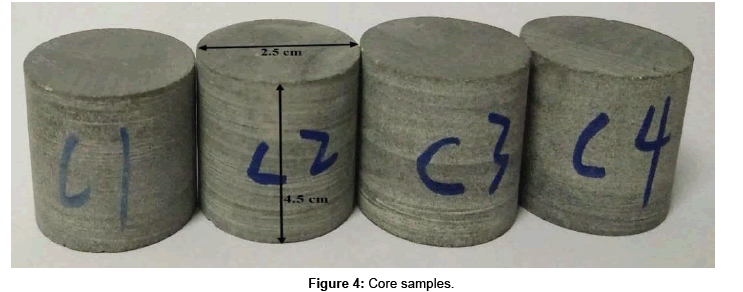
Core sample and brines
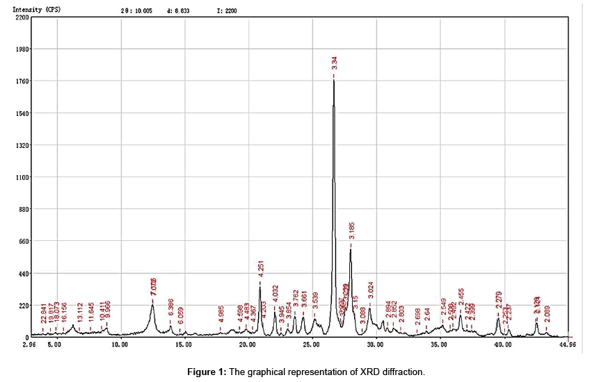
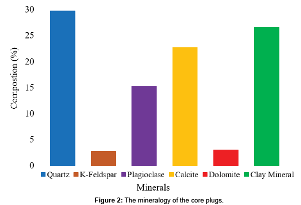
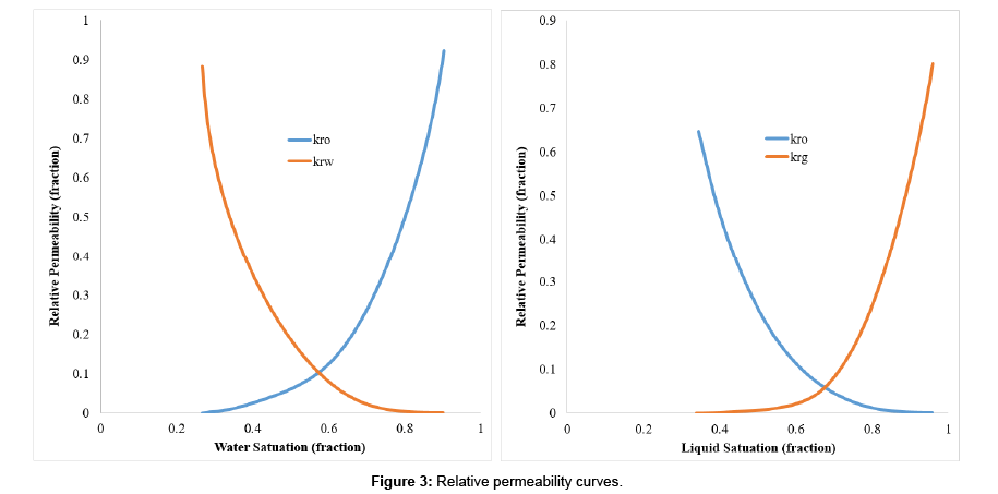
The core plug is from Chang formation in ordos basin. The diameter of the core plug is 2.5 cm and the length is 4.5 cm. The mineralogy of these samples are measured using x-ray diffraction (XRD) as shown in Figures 1 and 2 representing the mineralogy of the core plugs. The mineralogy of the core plugs shows that quartz (29.7 wt%), K-feldspar (2.7 wt%), plagioclase (15.3 wt%) calcite dolomite (3.0 wt%) were dominant non-clay minerals. The total amount of clay mineral (illite, smectite, chlorite) was 26.6 wt%. The relative permeability curves used in this study were generated based on our numerical core model using Lattice Boltzmann Method [11]. After calibration data and validity of the model with experimental work, the output of numerical core model used in this paper is shown in Figure 3.
Core saturation process
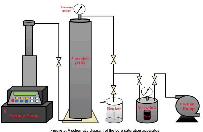
Unlikely, the conventional technique for saturating the tight reservoir core samples in the laboratory are not a suitable process due to low permeability. However, saturation of tight core samples needs either to adjust the conventional method or to find a new technique that can be used to saturate low-permeable cores. Yu and Sheng [10] modified a new technique initially proposed by Gamedi et al. [7,12] for saturating unconventional shale cores. Therefore, in this work, a new modified technique was used to saturate tight reservoir core samples. Before conducting the experiment, all core samples were dry weighted in order to be ready for vacuuming as shown in Figures 4 and 5 shows a schematic diagram of the core saturation apparatus.
Firstly, core plugs were engaged in high-pressure vessel#2 then vacuumed for two-days to assure that all air in the porous media and in vessel were vacated. Then syringe pump was used to inject oil from vessel#1 at constant rate into the high-pressure vessel#2 until its filled up with oil to assure better saturation achievement. The cores were saturated with oil under different pressures. At each pressure, saturated oil volume (Vos) was calculated by:
 (1)
(1)
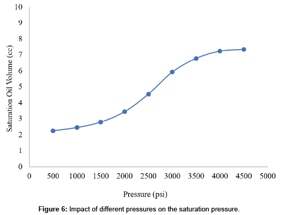
Where ws: weight of core saturated with oil, wd: weight of driedcore and ρo: oil density. Secondly, few cores saturated with water having different brine concentrations, then measured the saturated weight and finally those cores were re-saturated with the crude oil following the similar procedure as described above. Figure 6 shows the impact of the pressure on the saturated oil volume. After core saturation was accomplished and samples were prepared for the subsequent step of cyclic CO2 injection process.
Experimental Setup
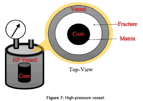
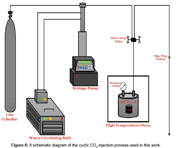
Initially, the core samples were taken from the saturation vessel#2 and they were weighted and recorded. Then the cores were kept vertically into high-pressure vessel which is placed in high temperature oven. Figure 7 shows the demonstration of high-pressure vessel. Considering the high-pressure vessel, the empty space and the core as our reservoir, hydraulic fractures and reservoir matrix, respectively. The CO2 cylinder was connected with high-pressure vessel through three-way valve and the experimental scheme utilized in this work as shown in Figure 8. It consists of a stainless steel high-pressure vessel, syringe-pump (ISCO brand, model 260D) is preferably designed for pumping purpose and it has an internal tube linked to a spontaneous flow and a pressure gauge controller (COEL K484P). The syringe pump has an internal tube of 266-ml and a acquittal pressure of up to 7251 psi (500 bar). The chamber cylinder of the pump is sheathed to keep their temperature stable using water-cooling system [13]. Furthermore, the high temperature oven used for heating purpose is automatically controlled electric heating system. The temperature was maintained at reservoir temperature (238°F) during the experimental stages.
Experimental procedure
In this study, the laboratory works were conducted for cyclic CO2 injection process and the core samples were saturated with and without water saturation during the experimental work. All the experiments were performed under reservoir temperature 238°F. The core samples were saturated only with oil as referred to (C-1) while the core samples were initially saturated with water at 80 psi for two hours and then saturated with oil at 800 psi for two days as referred to (C-2). Before starting any experimental process, first it is necessary to make sure that all the lines were connected into the system and the valves were checked and closed. The experimental technique for the cyclic CO2 injection process using this sort of investigational arrangement, initiates with filling the gas from the CO2-cylinder (at room temperature) into the chamber of the syringe pump. The temperature in the chamber of syringe pump is retained stable at 50°F using the water-cooling system (Julabo F34, Germany) [13]. Then regulator valve of CO2 cylinder is closed and the pressure is raised to 1450 psi inside the chamber. The equilibrium of the system (zero pump flow) needs about 15 to 20 minutes, and must be cautiously done to escape any trace flow that might lead to systematic error in the measured volume of the injected gas. Subsequently, after connected the whole system, the syringe pump was refilled by pressing the refill button, and the volume of gas had to reach 266-ml. Then, the valve of the CO2 cylinder was closed and the valve mounted at the top of the high-pressure vessel was opened, thus, allowing the syringe pump to inject the gas (CO2) into the vessel at constant pressure 1000 psi and at reservoir temperature 238°F. This process is called Huff or injection process. When the pressure inside the vessel reached to 1500 psi (monitored by pressure gauge that’s located at the top of the high-pressure vessel) it marked the completion of the CO2 injection process. Then CO2 injection valve was closed to allow the CO2 inside the vessel to soak (shut-in period) for a specific period. After the shut-in period was completed, the next step was to decompress the high-pressure vessel that had 2500 psi pressure of injected gas. The vessel was depressurized by opening the one-way valve that was connected with three-way valve and this process is called Puff or production period. Lastly, the production time was started when the pressure inside the vessel was depressurized to the standard pressure followed by the removal of core sample from the vessel and its weight was recorded after a specific production time. All these steps were considered as a single cycle of CO2 injection process. Thus, to do further cycles, above steps were repeated. In this work, the number of cycles were four for CO2 injection process at different production and soaking periods. The effect of soaking (shut-in) period was examined, the soaking period of 2, 4, 6 and 8 hours were applied. At the end of each cycle, different weights for different production times 15, 30, 60, 90 and 120 minutes, after the cyclic CO2 injection process were measured besides measuring the weight of the dry and the saturated core samples before conducting the cyclic CO2 injection process. After that, the data were ready to evaluate and discuss.
Results and Discussion
The results of cyclic CO2 injection process that have been conducted on the Chang formation in Ordos basin outcrop were investigated and the comparison between cores saturated with and without water during the cyclic CO2 injection process in terms of cumulative recovery factor which is the ratio of the produced fluid to the original fluid that saturated in the core samples and the effect of different parameters such as number of cycles, soaking period and production period were investigated.
Effect of number of cycles during cyclic CO2 injection process
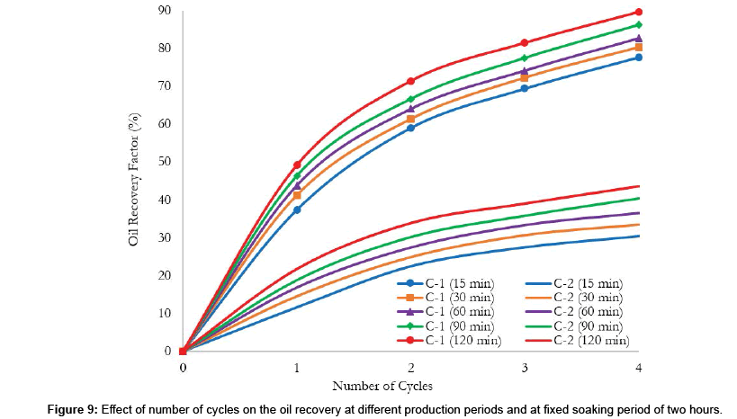
The effect of number of cycles on the oil production at different production periods, while keeping the shut-in period fixed for two hours. However, the experimental work initially conducted for the core C-1 to assure that the cyclic CO2 injection process was performed perfectly before conducting the main experiment for core C-2 as shown in Table 3, and then the results of both cases (C-1 and C-2) were analyzed and compared in order to assess the impacts of the water saturation on the oil recovery.
| Recovery Factor (%) | ||||||||||
|---|---|---|---|---|---|---|---|---|---|---|
| Core saturated with oil (C-1) | Core saturated with water and oil (C-2) | |||||||||
| NO. of Cycle | 10 min | 30 min | 60 min | 90 min | 120 min | 10 min | 30 min | 60 min | 90 min | 120 min |
| 1 | 37.43 | 41.24 | 43.86 | 46.37 | 49.18 | 11.64 | 14.57 | 16.95 | 18.86 | 21.75 |
| 2 | 59.09 | 61.35 | 64.05 | 66.67 | 71.43 | 22.47 | 24.9 | 27.52 | 30.26 | 33.87 |
| 3 | 69.46 | 72.24 | 74.17 | 77.47 | 81.51 | 27.46 | 30.69 | 33.45 | 35.87 | 39.00 |
| 4 | 77.74 | 80.28 | 82.73 | 86.22 | 89.64 | 30.40 | 33.47 | 36.63 | 40.48 | 43.60 |
Table 3: Reservoir fluid components.
The effect of number of cycles on the oil recovery for the cores saturated with/without water were shown in as Figure 9 for the core sample that only saturated with oil (C-1), one can observe that the highest oil recover was at the first two cycles at average of 21.66% (the recovery factor was 37.43% and 59.09% respectively) for the 15 minutes of production. However, the oil recovery factor then slightly increased after the second cycle until it reached the value of 77.74% at the end of the fourth cycle. For the production time of 30, 60, 90 and 120 minutes, the oil recovery factor was 41.24, 43.86, 46.37 and 49.18% respectively, and it increased at the average of 8.41, 8.37, 8.57 and 8.69% at each cycle correspondingly. Similarly, for the core sample that initially saturated with water and then saturated with oil (C-2), one can observe that increasing the number of cycles increases oil production recovery. For instance, the oil recover at the first cycle was of 11.64% for the 15 minutes of production and the second cycle, the oil recovery was of 22.47% which means that is nearly the twice recovery of the first cycle (10.83%). However, the oil recovery while considering water saturation was then slightly increased after the second cycle until it reached the value of 30.40% at the end of the fourth cycle. After the second cycle, the oil recovery factor keeps increasing at average of 4.35% at every cycle. For the production time of 30, 60, 90 and 120 minutes of C-2, the oil recovery factor while considering water saturation was 14.57, 16.95, 18.86 and 21.75% respectively, and it increased at the average of 4.38, 4.54, 4.92 and 4.97% at each cycle correspondingly. Furthermore, the comparison between C-1 and C-2, the cumulative oil recovery factor of the fourth cycle for production period of 15 minutes was 77.74% for C-1 and 30.40% for C-2 which means that the oil recovery factor of the core saturated with water and oil (C-2) dropped to almost 47.34% of the recovery factor of the core that only saturated with oil (C-1). Similarly, for the production period of 30, 60, 90 and 120 minutes were dropped 46.81, 46.10, 45.74 and 46.04% respectively.
Effect of production period on the oil recovery during cyclic CO2 injection process
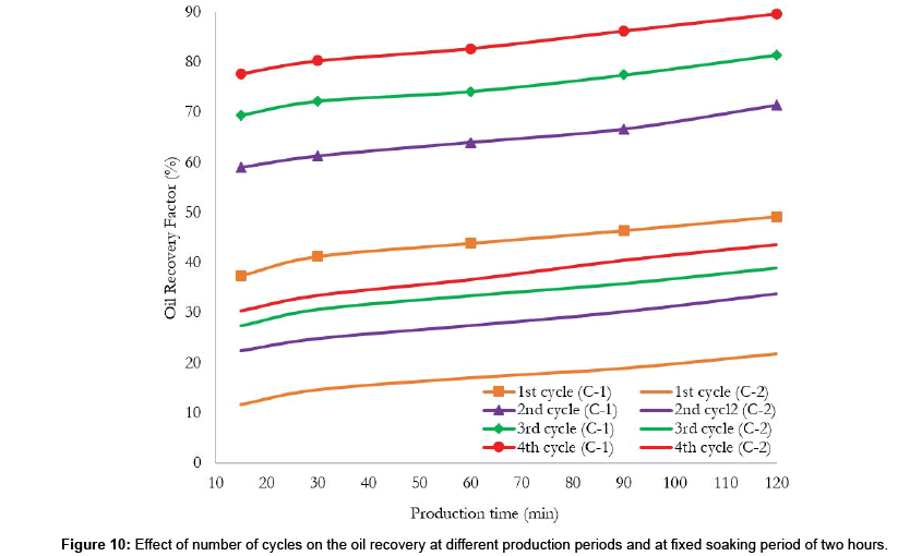
The effect of the production period on the oil recovery factor, the core samples were operated at constant pressure 1500 psi and the production periods were noted down for 15, 30, 60, 90 and 120 minutes. Figure 10 shows the effect of the production period on the oil production during cyclic CO2 injection process for the core samples that were saturated with and without water (C-1 and C-2) and at constant soaking period of two hours. However, the oil recovery for the core sample that only saturated with oil (C-1) during the first cycle at different production periods of 15, 30, 60, 90 and 120 minutes were 37.43, 41.24, 43.86, 46.37 and 49.18% respectively, taking into account that the oil recovery at each production period is increases with increasing the number of cycles until the end of the fourth cycle and after 120 minutes of production, the oil recovery was 89.64%.
Similarly, the effect of the production period on the oil production during cyclic CO2 injection process for the core samples that initially saturated with water and then with oil (C-2) and at constant soaking period of two hours. Though, the oil recovery from core C-2 during the first cycle at different production periods of 15, 30, 60, 90 and 120 minutes were 11.64, 14.57, 16.95, 18.86 and 21.75% respectively, taking into account that the oil recovery at each production period is increases with increasing the number of cycles until the end of the fourth cycle and after 120 minutes of production, the oil recovery was 43.60%. One can see from Figure 10 that the effect of water saturation on the production period has been observed when both cases (C-1 and C-2) were compared and the production period has an impact on the oil recovery factor.
Effect of soaking period on the oil recovery during cyclic CO2 Injection process
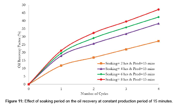
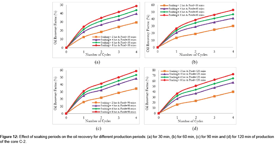
In order to examine the impact of soaking period on the hydrcarbon production during cyclic CO2 injection process, the core samples (C-1 and C-2) were operated under different soaking periods (2, 4, 6 and 8 hours) while keeping the soaking pressure constant at 1500 psi. The effect of soaking period on the oil recovery for production period of 15 minutes of the core sample C-2 as shows in Figure 11 at the first cycle, the oil recovery factor for two hours soaking period was 11.78%, after changing the soaking period to four hours the oil recovery become 17.98% which means its increases around 6.2%. Further extending the soaking period for six hours, the oil recovery was 19.59% (1.61% more than the soaking period of four hour) and extending the soaking period further more to eight hours, the oil recovery was 21.39% which is more than the soaking period of six hours by 1.67%. However, the oil recovery in the second cycle for the soaking period two hours was increased to 16.89% and the oil recovery kept increasing by almost 3.91% after the second cycle and reached to 32.45% at the end of four cycle. Furthermore, the oil recovery for the soaking period of six and eight hours at the end of fourth cycle were 39.61 and 47.23% with average increasing 4.3 and 4.7% respectively. Similarly, the effect of soaking period on the oil recovery for different production periods of 30, 60, 90 and 120 minutes and four cycles of the core sample C-2 were shown in Figure 12. Hence, one can conclude that oil production increases with increasing the number of cycles at fixed soaking period and additional expending the soaking period does not have any impact on the incremental oil production.
Conclusion
The experimental work demonstrated that cyclic CO2 injection process is an effective improved oil recovery technique and has capacity to recover an economical amount of hydrocarbon while considering the impact of water saturation on the oil recovery from tight reservoirs. This work accredited best techniques of retaining of fracturing fluids, enhancing the performance of cyclic CO2 injection process design and exploiting the oil recovery factor. The following conclusions can be drawn from this work:
i. The oil recovery increases with increasing the number of cycles. However, the increasing range will depend on the soaking and production periods.
ii. The longer production period will lead to more oil production However, extending the production period longer than optimum period will not additionally improve the oil recovery.
iii. The soaking period has an influence on the oil recovery and further extending the soaking period doesn’t improve any incremental oil recovery.
iv. The result shows that the oil recovery of the core sample initially saturated with water and then with oil at fixed soaking period, the oil recovery of the first and second cycles were 11.64% and 22.47% respectively, which is nearly the twice recovery of the first cycle (10.83%). After the second cycle, the oil recovery factor keeps increasing at average of 4.35% at every cycle.
v. The presence of water in the core has a negative impact on the oil recovery, thus it is demonstrated that the retention of fracturing fluids will improve the oil recovery.
vi. The experimental results confirmed that cyclic CO2 injection process have potential to improve the oil recovery.
References
- Mohammad RS, Zhang S Lu, S Syed J, Zhao X (2017) Simulation Study of Asphaltene Deposition and Solubility of CO2 in the Brine during Cyclic CO2 Injection Process in Unconventional Tight Reservoirs. World Academy of Science Engineering and Technology International Science Index Geological and Environmental Engineering Vol-11.
- Zhang K, Li Y, Hong A, Wu K, Jing G, et al. (2015) Nanofluid Alternating Gas for Tight Oil Exploitation Society of Petroleum Engineers.
- Wang L (2015) A Technical Review on Shale Gas Production and Unconventional Reservoirs Modeling Natural Resources 6: 141-151.
- Yang P,Guo H, Yang D (2013) Determination of residual oil distribution during waterflooding in tight oil formations with NMR Relaxometry measurements. Energy Fuels 27: 5750-5756.
- Wan T, Sheng JJ, Soliman MY (2013) Evaluate EOR Potential in Fractured Shale Oil Reservoirs by Cyclic Gas Injection. Unconventional Resources Technology Conference Denver Colorado 12-14 August pp: 1845-1854.
- Gamadi TD, Sheng JJ,Soliman MY (2013) An Experimental Study of Cyclic Gas Injection to Improve Shale Oil Recovery. Society of Petroleum Engineers.
- Chen C,Mohanty KK,Balhoff MT (2014) Effect of reservoir heterogeneity on improved shale oil recovery by CO2 huff-n-puff.Soc Petrol Eng.
- Song C, Yang D (2013) Performance evaluation of CO2 Huff-n-puff processes in tight oil formations.Soc Petrol Eng.
- Yu Y, Sheng JJ (2015) An Experimental Investigation of the Effect of Pressure Depletion Rate on Oil Recovery from Shale Cores by Cyclic N2 Injection. Unconventional Resources Technology Conference.
- Zi-Sen Wu (2016) Lattice Boltzmann Simulation of Fluid Flow in Complex Porous Media Based on CT Image. Journal of Industrial and Intelligent Information Vol-4.
- Gamadi TD, Sheng JJ,Soliman MY,Menouar H, Watson MC,et al. (2014) An Experimental Study of Cyclic CO2 Injection to Improve Shale Oil Recovery. Society of Petroleum Engineers.
- Abu-Eishah SI, Mohammad RS (2016) Phase Behavior of a United Arab Emirates Stock-Tank Oil and Carbon Dioxide at Reservoir Conditions: Experiments and Thermodynamic Modeling. Open Journal of Yangtze Oil and Gas 1: 1-22.
Select your language of interest to view the total content in your interested language
Share This Article
Recommended Journals
Open Access Journals
Article Tools
Article Usage
- Total views: 7037
- [From(publication date): 0-2018 - Dec 19, 2025]
- Breakdown by view type
- HTML page views: 5924
- PDF downloads: 1113
