Design and Simulation of Kiln for Optimum Fuel Use
Received: 19-Jul-2018 / Accepted Date: 02-Aug-2018 / Published Date: 07-Aug-2018 DOI: 10.4172/2576-1463.1000214
Keywords: Kiln; Gambit and fluent; Adiabatic; Conduction; Convection
Introduction
The major problem of the brick maker in Boye is, the traditional brick kiln does not have a kiln or firing house and this lead to heat loss. They use 28 m3 woods to fire 20,000 brick. In addition to this from the 20,000 bricks they get less than 50% brick. To reduce the above problems a new design of kiln is necessary [1]. There are many kiln designs from high-tech up to the traditional kiln but for the case of our country specially Jimma most of the brick makers are small scale and they are unable to afford the high-tech kiln design, therefore there should be compromise between the high-tech and the traditional one. So this project is proposed to improve the traditional kiln by considering the flue gas path, complete combustion inside the kiln with the controlled entry of air all the time and minimum fuel consumption and with an affordable price.
The disadvantage of using a rectangular kiln is shown in the Figure 1. In the case of Boye brick , after firing procces is completed the properly fired brick are inside the dome shape and the underfired bricks are above the dome shape. This helps to decide on the shape of the kiln. The main point one should bear in mind is that, using a kiln with a rectangular shape needs more heat distribution than the parabolic, but even if you distribute the heat effectively still there will be a loss because of the nature of the fire that is “it alwayse travel in side dome shape”.

Figure 1: (a) Picture taken from Boye, Jimma (b) Sketch for illustrating the brick manufacturing process in Jimma
Traditionally, in Boye the bricks are arranged in such a way that the flue gas flows in the space provided between the bricks. But the problem is spaces are not optimized to give maximum flue gas flow which leads them to heat loss. Figure 2 shows the traditional brick arrangements.

Figure 2: (a) Zigzag firing in the kiln (b) How brick are ordered in Boye, imma.
Materials and Methods
In present study, we have collected different data’s from the field. During firing process they build a kiln with dried brick itself in a rectangular shape and they open four firing door at the bottom (two in one side and two in the other side) and close those doors at the other side and finally they burn the brick. But after firing process has been completed more than half of the brick is wasted because of the poor firing and drying process. In this paper we only considering the firing process, and from that we select the dome shaped kiln (because of the flue gas travel in dome shape). And by increasing the number of flue gas path inside the kiln we are trying to simulate with gambit and fluent simulation software.
Parameters Of Heat Input And Output
Adiabatic flame temperature
In the absence of any work interactions and any changes in kinetic or potential energies, the chemical energy released during a combustion process either is lost as heat to the surroundings or is used internally to raise the temperature of the combustion products. The smaller the heat loss, the larger the temperature raises[2] (Table 1).
| Substance | h f° kJ/kmol | H (kJ/kmol) |
|---|---|---|
| C6 H12 06 | -118,050 | - |
| O2 | 0 | 8682 |
| N2 | 0 | 8669 |
| H2O(g) | 241,820 | 9904 |
| CO2 | 393,520 | 9364 |
Table 1: Chemical composition and enthalpy of formation of wood.
Hprod=Hreat (1)
Assumption 1: This is a steady-flow combustion process. 2: The combustion chamber is adiabatic. 3: Air and the combustion fuel are ideal gases [2].
 (2)
(2)
Drying energy
Drying energy is the energy used to dry the green brick, which is recoverable [3].
Energy in the brick is
Q=m × Cp × ΔT (3)
Where Q is total drying energy, Cp is specific heat, ΔT is change in temperature
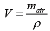
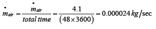
The volume of air needed for a unit kg of wood
 (4)
(4)
Where mair-mass of air, ρ-density
Heat loss through the chimney
Heat loss through the chimney is calculated as
Qloss=V × ρ × Cp × ΔT (5)
Where: Q is the heat content in kCal, V is the flow rate of the substance in m3/h, ρ is density of the flue gas in kg/m3, Cp is the specific heat in kCal/kg°C, ΔT is the temperature difference in °C.
Zigzag firing
Zigzag firing pattern is easily suitable in the existing system as there is no technology change as such. It is only process of arranging the bricks in order to get optimum flue gas path so that the bricks can be fired efficiently. Zigzag is already successfully being used in Varanasi cluster in 3 kilns. It is one of the most energy efficient technologies available [4].
Waste heat recovery
Waste heat is heat, which is generated in a process by way of fuel combustion or chemical reaction, and then “dumped” into the environment even though it could still be reused for some useful and economic purpose. The essential quality of heat is not the amount but rather its “value”. The strategy of how to recover this heat depends in part on the temperature of the waste heat gases and the economics involved. To calculate the heat loss through the chimney is
Q=V × ρ × Cp × ΔT (6)
Where Q is the heat content in kCal; V is the flow rate in m3/h; ρ is density of the flue gas in kg/m3; Cp is the specific heat in kCal/kg°C ; ΔT is the temperature difference in °C ; Cp (Specific heat of flue gas).
Calculations of insulating wall thickness
The new kiln was developed with the prime objective of decreasing the energy losses due to storage in walls and heat conduction to the ground. The energy absorbed by the walls and floor can be reduced by increasing the mass of the wall and floor coming in contact with high temperature. This can be achieved by providing a low cost insulation between the first layer of bricks facing the fire, and the remaining part of the wall or the floor. Several traditional kilns use ash as the insulator. In the new design, the insulation is provided by the air gaps in the floor as well as the wall. The wall is constructed using a rattrap bonded structure, which provides substantial air gaps in the wall.
The term “heat loss” commonly refers to the heat transfer of an object to its ambient environment. This implies that the object in question a wall, mathematically, the formula for calculating the heat loss of a system through conduction, expressed as follows.
To find the maximum heat loss through the kiln
Conduction heat transfer in rat trap wall: qw=kw (Tw–Ti)/(π α t)1/2 = (K)(A) (ΔT)/L (7)
Taking the firing time as hr, Kw=0.52, t=48
Where, kw=the thermal conductivity, α=thermal diffusivity, Tw=the temperature of the inner surface of the wall, t=time interval, and Ti=the initial temperature [5].
Convective heat transfer in rat trap wall: The convective heat transfer through the rat trap wall is is calculated using
Q=(U) (A) (T) ---- (8)
Where: U is the conductance, A is the surface area of object, ΔT is the temperature difference (T1 -T2)
qw=(U) (A) (ΔT), taking the firing time as 42 h, Kw=0.52,
Rbrick=L/K,
tw=tp+tair+2 × tbrick ,tbrick =0.06 m,tp=0.03 m,
Where, tw=thickness of the wall; tair=thickness of air; tbrick=thickness of brick
Heat transfer analysis and simulation
CFD codes are structured around the numerical algorithms that can tackle fluid problems. In order to provide easy access to their solving power all commercial CFD packages include sophisticated user interfaces input problem parameters and to examine the results [6]. Hence all codes contain three main elements:
1. Pre-processing
2. Solver
3. Post-processing
Results
Comparison of the temperature profiles for different kiln shapes
It can be seen that the rectangular kilns are less efficient than the square kiln due to their smaller cooling area of the same volume. In Figure 1 the properly fired bricks are inside the dome shape therefore, in order to account for the under fired brick which are out of the dome shape, the shape of the kiln should be square with a dome shaped. This statement can be clarified by using fluent software (Figures 3 and 4).

Figure 3:Temperature profiles of the brick inside the kiln at constant bottom wall temperature for rectangular kiln

Figure 4: Temperature profile of the kiln at constant bottom wall temperature for square dome shaped kiln.
From the above geometries, the square dome shaped kiln has smoother flue gas flow than the rectangular, therefore parabolic shape is selected for the entire analysis. Using the adiabatic flam temperature as an input, the simulation for different flue gas path can be seen in the preceding figures (Figures 5-9).

Figure 5: Kiln with no flue gas path.

Figure 6: For two step flue gas path.

Figure 7: For three step flue gas path.

Figure 8: For four step flue gas path.

Figure 9: For five step flue gas path.
From the above geometries increasing the flue gas path more than four step results in heat loss through the chimney, therefore four path step flue gas flow is optimum for this size kiln. For the four step flue gas paths, mass flow rate can be calculated from thermal equations.
Chimney height beyond 1 m
Increasing the height of the chimney beyond 1 m leads a high draft and a high temperature leaves through the chimney (Figure 10).

Figure 10: Chimney heights beyond 1m.
Thermal analysis
From the fluent result the exit temperature of the kiln is around 366°C. By using this value mass flow rate of the flue gas can be calculated. First let’s calculate the mass flow rate of the air introduced in to the combustion chamber. In order to get the amount of oxygen needed, first fix the type of fuel used for this kiln. Since barrel land wood type is available in Jimma and have heat capacity higher than the eucalyptus tree therefore it can be used as a fuel source for this kiln (Table 2).
| C | H | O | N | S | CI | ASH |
|---|---|---|---|---|---|---|
| 35 | 4.30 | 59.30 | 0.4 | - | - | 1.00 |
Table 2: Chemical composition of fuel used.
On weight basis: Taking one 1 kg of wood as a base, the amount of oxygen required to burn carbon in 1 kg of wood is
 (9)
(9)
1 kg C =32/12 kg O2
X=0.9333 kg
Similarly for combustion of hydrogen the wood contains:
 (10)
(10)
For 0.043 kg H2 oxygen required is=0.344 kg
The total oxygen required is (0.9333+0.344=1.2773) kg/kg of wood. But 0.593 kg of oxygen is available in the wood. Therefore the total oxygen needed is:
1.2773-0.593=0.6843 kg/kg of wood
The amount of excess air added for solid fuel is 20% [4]. Therefore the oxygen to be supplied is:
=O2req+20% O2
= 0.6843+20/100 × 0.6843= 0.82116 kg/kg of wood
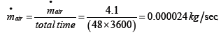
Air contains 23% of oxygen by weight. The weight of the air to be supplied is
= 0.82116 × 100/23= 4.1058 kg/kg wood
To calculate the volume of air needed for a unit kg of wood
The density of air at atmospheric pressure and temperature is taken for Jimma 0.82 bar and 300 k respectively [7].
ρ = p/RT (11)
Where, p=82 kpa
R=0.287 kpa/kg.K
T=292.15 K
=82/(292.15 × 0.287)=0.98 kg/m3
V of air needed/kg of wood = mair/ρ = 4.1058/0.98= 4.2 m3 (Table 3)
| Types of brick | Cp J/kgK | ρ | Cv (W/mK) |
|---|---|---|---|
| Brick | - | 1920 | 0.720 |
| Fire brick | 829 | 2080 | 1.296 |
| Clay | 880 | 1790 | 1 |
| Fire clay brick | 960 | 1460 | 1.3 |
Table 3: Property table for brick.
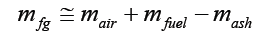
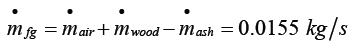
Energy balance: The heat to be supplied by the fuel=energy in the bricks+drying energy+heat loss through the chimney.
Drying energy: It is the energy used to dry the green brick, which is the recoverable
Energy in the brick is Q=m × Cp × ΔT Mass of the green brick is 2.1 kg, therefore
=2.1 kg × 880 J/kgK × (948-19) K
=1.72 MJ
Drying energy: Drying energy (MJ)=Qdrying=wet mass of green bricks minus dry mass of green bricks x energy required to evaporate water
(2.591 MJ/kg) (12)
= (2.1-1.7) 2.591 MJ/kg
=1.0364 MJ
Heat loss through the chimney is calculated as
Qloss=V × ρ × Cp × ΔT
From the simulation of the chimney the temperature at the exits is around 366°C there for
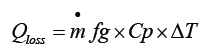
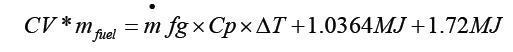
The heat to be supplied by the fuel=energy in the bricks+drying energy+heat loss through the chimney
Totalheat=CV × mfuel (13)
Combining equation (2), (8), (4) and (9) gives
But is calculated as
 (14)
(14)
mash=0.25*mfuel
4.1 kg/kg wood+0.75 mfuel
Therefore, total heat required to fire 1 kg of wood is
= (4.1 kg/kg wood+0.75 mfuel) × Cp × ΔT+1.0364 MJ+1.72 MJ
CV=16.74 MJ/kg, Cp=0.24 kCal/kg/°C × 4.186 J/cal=1.00464 KJ/ kg/°C ,
ΔT=366-19=347°C (from the Fluent result)
16.74 × 10³ KJ/kg × mfuel=(4.1 kg/kgwood+0.75 mfuel × 1.00464 KJ/ kg/°C × 347°C + 1.0364 × 10³ KJ +1.72 ×10³ KJ
mfuel = 2679.7 kg
Total heat=Cv × mfuel = 16.74 × 2679.7=44,858.6 MJ
To find the mass flow rate of wood
=4.2 m3/kg of wood × mwood = 11,254.74 m3
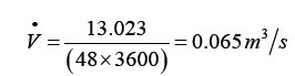
The mass flow rate of the flue gas supplied to the kiln from the combustion chamber is
Using this mass flow rate and adiabatic flame temperature the kiln can be simulated as follow
Input 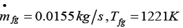
Convergence curves of energy velocity and residuals
The graphs got converged properly for constant temperature at bottom wall for 200 steps of a time step of 1 second (Figure 11).

Figure 11: The graph converged with a constant temperature of 1221.15 k.
Comparison of the temperature profiles
The graph for the temperature of the fluid at constant temperature is found out. The maximum temperature at the bottom of the wall and at the middle was 978 K and maximum temperature is 1221.15 K. The bricks are arranged in such a way to get uniform flow arrangements therefore the bricks can be fired properly without loss. And the figures (Figures 12-15) below show that, the flue gas flow for different mass flow rates. Let’s start from the initial mass flow rate (0.0155 Kg/sec) which is calculated from thermal analysis formulas.

Figure 12:Temperature profile for four flue gas path and 1m chimney height and 0.0155 kg/sec of mass flow rate.

Figure 13: Temperature profile for four flue gas path and 1m chimney height and 0.018 kg/sec of mass flow rate.

Figure 14: Temperature profile for four flue gas path and 1m chimney height and 0.02 kg/sec of mass flow rate.

Figure 15: Temperature profile for four flue gas path and 1m chimney height and 0.022 kg/sec of mass flow rate.
If the mass flow rate of the flue gas in increased above 0.022 kg/ sec the flue gas with a large temperature exits through the chimney therefore the optimum mass flow rate for this kiln size is 0.022 kg/sec and the total mass of fuel used is
0.022 × 3600 × 48=3801.6 kg
Total energy=CV × mfuel 3801.6 × 16.74=63,638.784 MJ
SEC =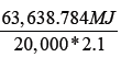 =1.52
=1.52
From the above result using the newly designed kiln reduce energy consumption of 68716.716 MJ as compared with the traditional kiln.
Waste heat recovery
Q=V × ρ × Cp × ΔT
Q=0.022 × 0.24 ×1.186 × (366-19) = 1.83216 kCal/kg
By installing dryer for the brick drying purpose, this heat can be recovered to pre-heat the green brick.
Calculations of insulating wall thickness
Conduction heat transfer in rat trap wall
qw=kw ( Tw – Ti)/(π α t)1/2 = (K)(A) (ΔT)/L ,taking the firing time as hr , Kw=0.52, t=48
Heat transfer through conduction
Q=KAT/L=qw=kw (Tw – Ti)/ (π α t) 1/2
2 × 0.52 × (657-25)/(π × 5.2 × 10-7 × 48)½= 0.5 × 9 × (657-25)/L
L=24.8 cm
Convective heat transfer in rat trap wall
The convective heat transfer through the rat trap wall is calculated using
Q=(U) (A) (T)
AUt=1/Rp+1/Rbrick+Rair+Rbrick+1/ho,
Resistance of plaster = L/K =0.03/0.14= 0.214 K/W
Resistance of air gap = L/0.026.
Resistance of air film on outside surface = 1/ho
= 1/ 10 W/mK = 0.1 K/W
Resistance of insulating firebrick = 0.06/1.25 W/mK =0.048 ×2=0.096 K/W
Rtotal= 0.096+0.0588+tair/0.026+0.214= 0.3688+tair/0.026
qw=(U) (A) (ΔT)
From Figure 15 the maximum wall temperature loss through the kiln is taken as the average temperature at the inlet and exit of the kiln therefore:
Tave=(948+366)/2= 657°C
0.52 × 9 × (657-25)/0.248=(1/(0.3688+tair/0.026)) × (657-25) × 9
tair =0.028 m=2.8 cm
tw =3+6+6+2.8 =17.8 cm
Conclusion
Sustainable small-scale brick production Energy data from brick production are often unreliable and incomparable; a standard method for assessing energy efficiency is required to make systematic progress and share lessons. New kiln design have been made for reducing the energy absorbed in the kiln wall and the floor by introducing air gaps and also reducing the thickness of the wall. Use of rattrap bonding in the wall, and increasing the gap that flue gas travel between the brick has helped to achieve the result. On the basis of the assessment, which result in about 81.7% savings in fuel as compared to the original kiln of the same brick output.
Acknowledgement
The authors expressing profuse gratitude to those who gave abundance support to make this research work accomplished. Especially, Jimma brick makers, Mr Andia, Tesfu and Ms Medani for their tremendous help and support. We must acknowledge the Mechanical Engineering Department staff of the Addis Ababa and Aksum University for their being cooperative and providing us the facilities to conduct this work.
References
- Amaha S, Pydi HPR (2014) Performance analysis of a kiln for locally manufactured clay brick. Int J Sci Eng Technol Res 3: 1282-1283.
- Cengel YA, Boles MA (2005) Thermodynamics an Engineering Approach (5th Edn). pp: 765-773.
- Cengle YA (2006) Heat Transfer Practical Approach (2nd Edn), Boston pp: 6-13.
- Bureau of Energy Efficiency (2010) Technology Upgradation from Straight Line to Zigzag Firing Brick SME Cluster.
- Ravi MR, Dhar PL, Kohli S, Arora L (2002) Energy Audit of Pottery Kilns in Gramodaya Sangh Bhadrawati, NIRI Project Report, Delhi. pp: 7-12.
Citation: Amaha S, Dama T (2018) Design and Simulation of Kiln for Optimum Fuel Use. Innov Ener Res 7: 214. DOI: 10.4172/2576-1463.1000214
Copyright: © 2018 Amaha S, et al. This is an open-access article distributed under the terms of the Creative Commons Attribution License, which permits unrestricted use, distribution, and reproduction in any medium, provided the original author and source are credited.
Select your language of interest to view the total content in your interested language
Share This Article
Recommended Journals
Open Access Journals
Article Tools
Article Usage
- Total views: 3845
- [From(publication date): 0-2018 - Jul 02, 2025]
- Breakdown by view type
- HTML page views: 2986
- PDF downloads: 859