Dual System Configuration for Earthquake Safety
Received: 16-Jan-2013 / Accepted Date: 24-Jun-2013 / Published Date: 26-Jun-2013 DOI: 10.4172/2168-9717.1000108
Abstract
Structural control through integration of passive damping devices within structures has proven to be a most promising strategy for earthquake safety. Within this research field, the concept of adaptable dual control systems has been initially proposed for application in frame structures supplemented with a cross cable bracing with closed circuit and a hysteretic damper of steel plates. The control mechanism enables the elastic response of the primary structure through energy dissipation only effected by the damper that is activated by all bracing members. In extending the applicability range of the control concept in both, in engineering and broader architectural context, and further improving the controlled system’s performance, an alternative configuration of the bracing-damper mechanism is investigated. Following the construction design of the control system members a numerical dynamic analysis of a SDOF system is performed for three representative international earthquake motions of differing frequency contents. The characteristic stiffness and yield force of the integrated damper are investigated in their optimum values for achieving high energy dissipation capacity of the system, while preventing possible increase of the maximum base shear and relative displacements.
Keywords: Structural control; Cable braced frame; Hysteretic damper; Dual system
73916Introduction
The design of frame structures with additional control members for earthquake resistance refers primarily to the requirement for the primary systems to exhibit essentially a linear elastic behavior under seismic actions [1-3]. A reduction of the energy dissipation demand on primary structural systems was successfully aimed at by a number of researchers through integration of damping devices, such as passive metallic yielding-, friction-, viscoelastic- and viscous damping devices [4-7]. In principle the damping devices are added in moment resisting frames attached on steel bracings that may be of accountable selfweight and stiffness [8-11]. The bracing components consist of steel members stressed in compression, tension and bending, and increase the overall stiffness of the system [12,13]. In addition their seismic control resistance weakens by the fact that under cyclic loading in every half-loading cycle the compression diagonal buckles and it therefore cannot participate in the energy dissipation process. On the other side, a conventional bracing consisting only of cables is not suitable for earthquake resistant structures, due to the fact that the members become slack under their tension yielding and compression buckling.
Driven by certain advantages in architectural, aesthetic, constructability and economic context, the implementation of tension only bracings with damping devices in frame structures may be realized through the development of suitable bracing-damper configurations, whereas all bracing members contribute during the entire load duration to the operation of the integrated damper. An optimization of the control system’s operation principles for earthquake structural resistance may thus be achieved. This concept was initially followed with the Pall- Marsh friction mechanism using slender cross braces [14]. In principle the rectangular damper deforms into a parallelogram, dissipating energy at the bolted joints through sliding friction. The kinematics of the system prevents the diagonals to buckle in compression; with the completion of a loading cycle, the hysteresis loops are identical for all bracing members. An alternative friction mechanism configuration with cross braces has also been proposed in [15].
Recently proposed control systems that consist of hysteretic dampers and slender bracing members are based in their operation on relative displacements between the tension members. Hysteresis is achieved through optimization of the integrated hysteretic dampers plates’ section. The cross braces with the articulated quadrilateral with steel dissipaters work only in tension, whereas energy dissipation develops through elasto-plastic flexure of the steel plates with varying depth [16]. A similar cross cable bracing configuration with a central energy dissipater consisting of two steel plates that are interconnected through a rotational spring has been proposed [17]. Under seismic excitation four cables in tension rotate the steel plates in opposite directions. The remaining cables, which connect across the shortened diagonal, are stressed elastically in compression and do not become slack, when the loading direction changes, due to the permanent rotation of the steel plates.
The research inquiry of utilizing the performance of mild steel in terms of strength, flexibility and minimal structural weight with the requirement for a smooth, non-coupled operation of the tensiononly bracing-damper mechanism to the primary system under dynamic excitations initiated related studies [18] and has led to further development of possible configurations for Adaptable Dual Control Structures, ADCS [19]. ADCS consist of a cable bracing with closed circuit and a hysteretic damper of steel plates. During strong ground motions relative displacements between the bracing and the frame member interconnected through the hysteretic damper yield to the damper’s own deformations and energy dissipation. ADCS is only responsible for the earthquake forces and enables in all cases the elastic response of the primary system.
In principle, ADCS introduce a prototype connections design for the bracing members, utilizing rotating mechanical discs. The connection principle may be applied in different bracing configurations that share common features in respect to the kinetic model and the control behavior of the system. Furthermore, the hysteretic damper applied in ADCS, may follow the section principles of hysteretic dampers subjected to shear forces at their connections. The dampers consist of X- or triangular-shaped steel plates for achieving uniform deformation curvatures over the sections’ height, as applied in the examples of ADAS- and TADAS-devices [20-22]. The present analysis refers to a particular ADCS-configuration of a portal- and a chevron bracing, ADCS1. The specific configuration differs from the cross bracing mechanism initially proposed in [18], ADCS0, for further improving the overall seismic performance of the controlled system and providing an alternative structural form in architectural context.
In the following sections ADCS1 configuration is introduced and the dynamic response behavior of the controlled SDOF-model is numerically investigated, based on three selected international strong ground motions with different frequency contents. The predominant design parameters for characterizing the ADCS1 response are defined as a function of the damper’s elastic stiffness and yield force. ADCS1 effective response behavior in terms of energy dissipation maximization, without increase of the system’s maximum base shear and relative displacements is verified.
Design Configuration
ADCS are based on a dual function of the component members, resulting in two practically uncoupled systems. The primary frame is responsible for the normal vertical and horizontal forces, while the bracing-damper mechanism, for the earthquake forces and the necessary energy dissipation. ADCS enable the primary frame to respond elastically, while inelastic action is handled by the hysteretic damper acting as a second line of protection. In principle the control concept is based on achieving predefined performance levels through the development of deformation, rather than stiffness.
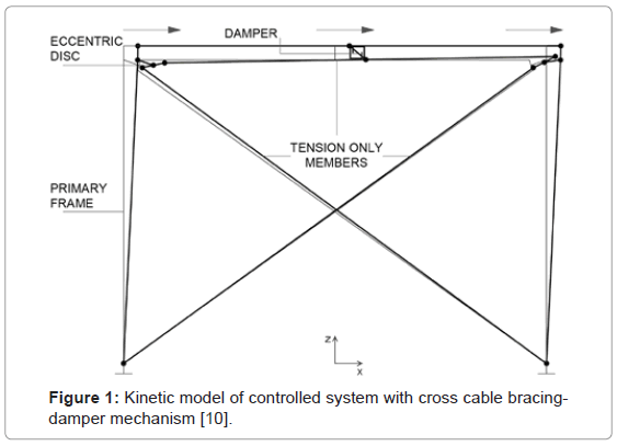
An initially proposed ADCS-configuration consisted of two cross cables and a horizontal one, all interconnected through eccentric rotating discs at the frame’s joints [18]. A hysteretic damper of rectangular steel plates was connected between the horizontal cable member and the primary beam. During strong ground motions relative displacements between the bracing and the beam of the frame lead to energy dissipation through the damper’s own deformations. The kinetic model of this cross bracing-damper mechanism is exemplified in Figure 1.
Figure 1: Kinetic model of controlled system with cross cable bracingdamper mechanism [10].
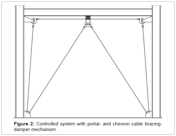
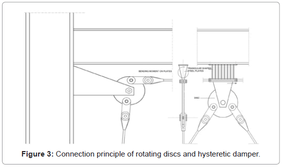
In improving the activation and performance of the hysteretic damper a differing configuration, of a portal- and a chevron bracing, is investigated in the present paper. All cables of the proposed control system are fixed connected at the bottom of the columns and are free to move horizontally at the connecting joints of the frame (Figure 2). A hysteretic damper is placed between the beam and the horizontal member of the portal cables. The latter are connected to the eccentric discs of the primary frame´s joints and the adjacent columns at the supports. An additional pair of chevron braces is connected to a middle eccentric disc fixed at the lower horizontal connecting plate of the damper. The hysteretic damper consists of a series of triangular shaped steel plates, welded on two horizontal plates (Figure 3). The plates’ characteristic shape enables uniform deformation curvatures over the sections’ height. Therefore all section lines reach their maximum yielding potential at the same time under the developed shear forces.
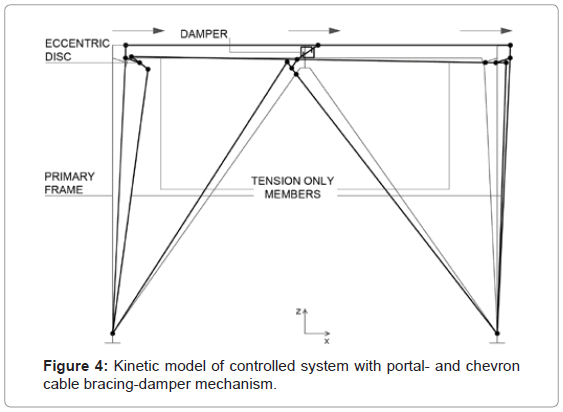
The kinetic mechanism of ADCS1 is activated during the dynamic excitation by the horizontally induced motion at the base of the structure. In every half-loading cycle the respective displacement of the primary frame is followed by the cables through rotations of the eccentric discs. The rotations result to respective axial displacements of the connection joints to the cables, stretching the members. Since the bracing members form two independent kinetically closed polygon shapes, ideally the reactions on the primary frame are neutralized and the members remain under tension (Figure 4). The portal bracing is primarily responsible for the relative displacements of the bracing to the primary system leading to deformations of the interconnected hysteretic damper, whereas the chevron bracing through its re-centering action, is responsible not only for further increase of the damper’s deformations and the resulting energy dissipation, but also for decrease of the sensitivity of the control mechanism to the earthquake loading. The optimization of the bracing-damper mechanism involves tuning between the stiffness, the yield force and the inelastic deformations of the hysteretic damper, so that the energy flow in terms of hysteresis by the damper and the elastic strain energy in the tension-only bracings and the primary frame is effectively managed during the earthquake induced motion. In addition the maximum base shear and the relative displacements of the controlled system should hold in bounds with the respective responses of the primary system.
System Model
The finite element analysis of ADCS relies on a simplified model, whereas non-linearity is only addressed to the hysteretic damper, i.e. the non-linear link. The dynamic behavior of the controlled SDOF system was examined with the software program SAP2000. A typical geometry was assigned for the ideal 2D-model of a steel moment resisting frame of 6.0 m long beam and 4.5 m high column members. The preliminary analysis was completed for a number of combinations of characteristic design variables. IPBv500 sections were assigned for the columns and IPBL550 for the beam (S235, E=2.1×10⁴ kN/cm2, ρ=78.5 kN/m3). The dimensioning of the members fulfilled Eurocode 3 design requirements, having assumed a static vertical load of 1200 kN, a horizontal wind load of 15 kN and 25% of the vertical load as static equivalent seismic load. The primary frame’s fundamental period results to T=0.34 s and its stiffness to k=41717.37 kN/m.
In the numerical analysis of the proposed control system the cables have constant diameter of dc=20 mm (E=1.6×10⁴ kN/cm2, fe=140 kN/ cm2) following initial investigations by the authors that concluded in a practically insignificant influence of the members’ stiffness to the energy dissipation performance of the integrated damper [23]. The effective bracing’s stiffness results from the respective values of the vertical and diagonal braces connected in parallel, and amounts to kb=2895.34 kN/m. The cables were modeled as frame objects with zero compression limit and were assigned a suitable pretension stress, which would keep the members straight and taut when they are deformed. Finally each disc was modeled as a composition of three short frame members, assigned with large stiffness values to represent the real property of a mechanical disc’s shaft.
Mechanical Properties of Hysteretic Damper
ADCS may result to significant energy dissipation for the selected earthquake cases of the analysis, provided that the geometrical and mechanical parameters of the elements are predefined respectively. ADCS response for the desirable level of seismic protection depends primarily on two main factors:
(1) The effective values of the relative stiffness of the primary frame, the bracing and the hysteretic device at the target displacement that leads to the selection of the design elastic stiffness of the damper, kd, given by the following equation:

where h is the steel plate’s height, b is the -width (fixed to the beam), t is the -thickness and n is the number of steel plates (S235, E=2.1×10⁴ kN/cm2, ρ=78.5 kN/m3)
(2) The load, at which the damper yields and dissipates energy through its inelastic yielding deformation, Py, given by the following Equation:

Where fy is the yield stress (S235, fy =24 kN/cm2).
Hysteretic dampers may exhibit a bilinear- or trilinear hysteresis, an elasto-plastic or rigid-plastic behavior. The damper used in ADCS was modeled as a non-linear link element. The damper’s force-deformation relationship for the respective degree of freedom that corresponds to shear follows the hysteretic model described as Wen plasticity property type of uniaxial deformation. The results were calculated based on this characteristic hysteresis model, mathematically described as follows:

where f is the force, d is the induced displacement, k is the elastic spring constant, i.e. initial stiffness, “yield” is the yield force, “ratio” is the specified ratio of the post-yield stiffness to the elastic stiffness, i.e. secondary stiffness ratio, and z is an internal hysteretic variable that evolves according to the following differential equation:
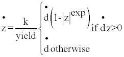
where “exp” is an exponent greater than or equal to unity (practically about 20) and z is a path dependency parameter. SAP2000 provides the analytical model described in Equation (3), which represents the hysteretic behavior of the device. During the dynamic motion, inertia forces are activated by all concentrated masses, including the mass distributed on the rigid plates’ section. The inertia forces contributed by the damper are expressed through the resistance to the angular acceleration. The related resistance is given as the integral of the “second moment” about an axis of all the elements of mass dm, which compose the body of the steel plate used for added damping, MMI, as follows:

where MMI is the mass moment of inertia (RI in SAP2000 software), software), ρ is the density of the material used, V is the volume of the section shape and r is the perpendicular distance from the axis to the arbitrary element dm
The damper provides energy dissipation through its hysteretic behavior. The Damper Ratio, DR, that describes the response of ADCS as a function of the damper’s stiffness and yield force may be introduced, as follows:

For the investigation of the sensitivity of the system’s seismic control effectiveness to variations of the characteristic parameters of DR, a range of damper’s stiffness values between 150 kN/m<kdy
Input Seismic Records
The primary frame and the controlled system were evaluated in their dynamic behavior under the action of three different selected strong earthquake excitations with differing energy content characteristics (Table 1). The earthquake records represent moderately long, extremely irregular motions. The predominant periods of the ground motions range in their respective displacement response spectra between 1.5-3.0 s. In the analysis no critical damping was considered for the model or the dynamic loading motions.
| Seismic Case | Record | Station | Mw | PGA [g] | Duration [s] |
|---|---|---|---|---|---|
| A | El Centro 1940 | Imperial valley, component 180 | 6.9 | 0.348 | 53.76 |
| B | Kobe 1995 | JMA, component 0 | 6.9 | 0.810 | 48.00 |
| C | Northridge 1994 | Olive view, component 90 | 6.7 | 0.604 | 30.00 |
Table 1: International seismic input records.
Systems Dynamic Response
Natural period
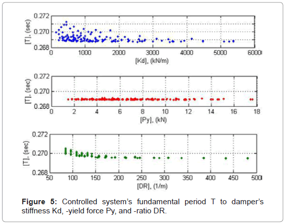
Earthquake resistant systems are at first place characterized by their fundamental period. Since the controlled system’s period is only associated to the behavior of the system in its linear elastic range, it depends only on the two components’ stiffness, i.e. the primary frame’sk and the damper’s stiffness kd that are linked in parallel, while it remains independent from Py which defines the nonlinear behavior of the damper. Compared to the primary frame’s fundamental period of T=0.34 s, the controlled system’s period decreases to the range of T=0.27 s. This may provide first indications in respect to possible stiffness-, base shear- and related input energy variations through the integration of ADCS1 within the primary frame. For verification purposes the relation of the controlled system’s period in respect to all damper’s characteristic parameters, kd, Py and DR, concluded in Figure 5.
Energy dissipation
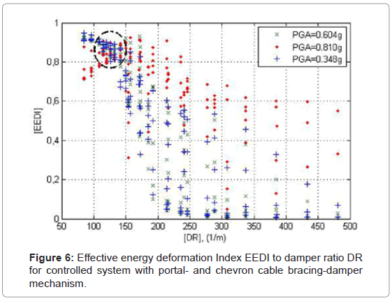
The controlled system may be tuned to a specific earthquake hazard protection level as defined by the designer in representative quantifiable energy measures of deformation. The system may be designed for a target performance level. In the present study the performance index for structural safety was defined as the Effective Energy Deformation Index, EEDI that physically represents the amount of input seismic energy dissipated by the hysteretic device for the entire seismic input time duration. A number of 397 combinations of assigned values of the damper’s stiffness and -yield force in terms of DR have been used in the parametric analysis for all seismic cases. The ratio values of the hysteretic energy to the input energy of the system are presented in Figure 6, calculated for each value of DR. The energy ratio variation is marked on the y-axis, while on the x-axis the variation of the design parameter DR is marked.
The selected non-linear parameter, DR, is proposed to characterize the dynamic response behavior of ADCS1, and varies between a minimum value of DR=84.22 1/m and a maximum value of DR=481.3 1/m. This range of DR values is adequate for the selection of the predominant characteristic design parameters of the damper. Maximum energy dissipation for all three loading cases is achieved within a DR magnitudes range of 100<DR<150 1/m. ADCS1 energy dissipation is in particular unsuccessful for high values of DR, i.e. DR>400 1/m, especially for the low peak ground accelerations, PGA<0.60 g. ADCS1 performed comparatively better in the seismic case B with high peak ground acceleration, PGA>0.80 g. The high values of DR result from respective high values of kd that lead to an almost rigid-plastic behavior of the damper and cause certain time-delay in the initiation of the energy dissipation process.
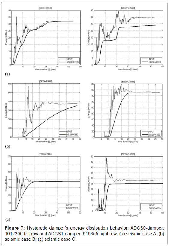
The time variations of the system’s input- and dissipated energy leading to highest energy dissipation performance by ADCS0 and ADCS1 for all three seismic loading cases are shown in Figure 7. ADCS0 optimum mechanical properties of DR=265.45 1/m, kd=3910 kN/m, Py=14.73 kN and  =1.65, as proposed in [18], are derived in the present analysis by using ten triangular-shaped steel plates, instead of rectangular ones originally considered, of t=1.2 cm, h=20 cm and b=5 cm each (damper: 1012205). ADCS0 has been implemented in the same primary system and analyzed in its energy dissipation performance for the three seismic loading cases (Figure 7, left row). EEDI reaches 92.43% in seismic case A and 90.61% in -case C. In the seismic case B with highest peak ground acceleration the controlled system’s EEDI remains comparatively poor with 58.86%.
The selected geometry of the damper’s steel plates in ADCS1 for highest energy dissipation performance and limitation of the system’s responses as described in the subsequent sections, accounts to n=6, t=1.6 cm, h=35 cm and b=5 cm (damper: 616355). The respective optimum DR value amounts to 114.3 1/m ( kd=1003.10 kN/m, i.e.k' =kd /k =0.024,  =2.89, Py=8.78 kN). EEDI reaches 86.38% in seismic case A, 81.64% in case B and 85.13% in case C. In the parametric study the damper’s plates’ height, h, proved to influence stronger the system’s behavior than the other geometric parameters.
Base shear
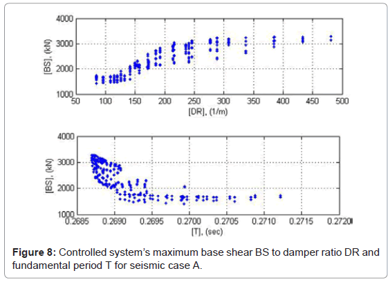
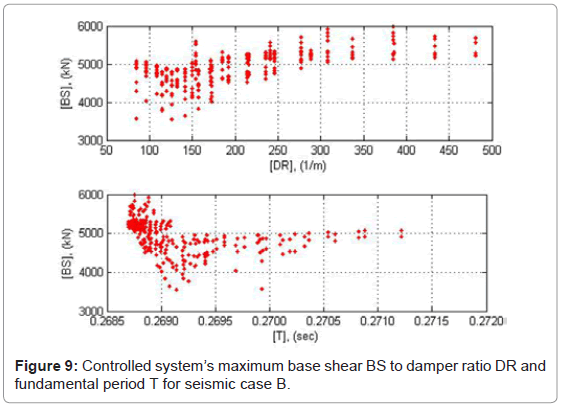
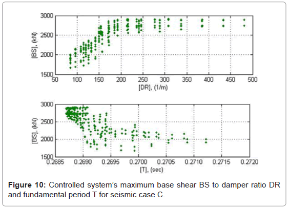
Observations on the sensitivity of the yield strength to the hysteretic and total energy input lead to the conclusion that the energy input tends to increase as to the system’s stiffness after the damper’s yielding [24]. A possible increase in the energy input back to the seismic control system may lead to damage under repeated excitation cycles. ADCS1 base shear responses under the three strong ground motions used in the analysis indicate some basic characteristics of the controlled system’s performance. The magnitudes of base shear are presented in absolute values in Figures 8-10 as a function of DR and T. The parallel presentation of the results in relation to T serves for verification of the response relations derived as to DR.
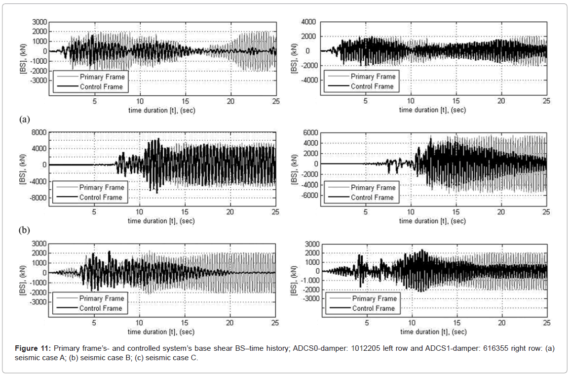
The maximum base shear of ADCS0 for a DR value of 265.45 1/m (damper: 1012205) compared to the primary frame’s response yields to a respective decrease of 23% in seismic case A and 2% in case C. In seismic case B the maximum base shear increases by almost 24% (Table 2). On average for all seismic cases considered no variation of the maximum base shear can thus be registered by the controlled system. As far as ADCS1 is concerned, in no analysis cases the maximum response value increased significantly. Within the selected DR values for optimum energy dissipation performance of ADCS1, i.e. 100<DR<150 1/m, the base shear of the controlled systems has the lowest values. Compared to the primary frame’s base shear, ADCS1 maximum base shear decreases for a DR value of 114.3 1/m (damper: 616355) by 8% in seismic case A and by 13% in case B, whereas in case C it increases by almost 2% (Table 2). The average decrease of the maximum base shear amounts to 6.3%, whereas the energy dissipation exceeds in all cases a benchmark of 80% of the input seismic energy
| Seismic Case | Max. base shear [kN] | Energy dissipation ratio [%] | |||
|---|---|---|---|---|---|
| Primary Frame | ADCS0 | ADCS1 | ADCS0 | ADCS1 | |
| A | 2102 | 1619 | 1932 | 92.43 | 86.38 |
| B | 5570 | 6880 | 4830 | 58.86 | 81.64 |
| C | 2304 | 2253 | 2340 | 90.61 | 85.13 |
Table 2: Primary frame’s- and ADCS maximum base shear and energy dissipation.
Figure 11 shows the time-history for the first 25 s of the primary frame’s base shear to the controlled systems’ base shear under the three loading cases, for ADCS0 on the left row and ADCS1 on the right row.
Relative displacements
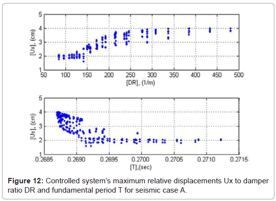
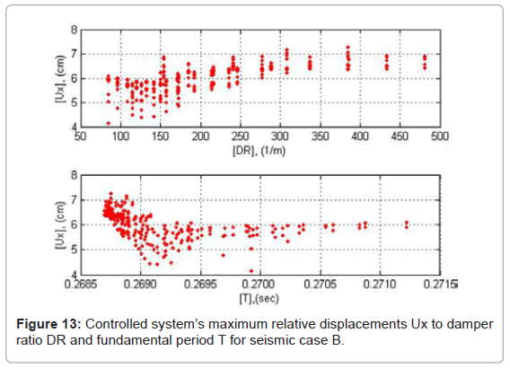
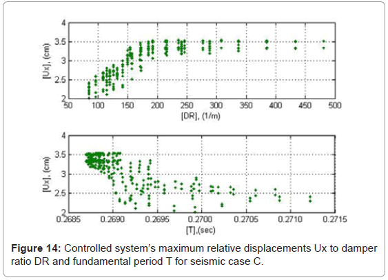
The relative displacement magnitudes of ADCS1 are presented in absolute values in Figures 12-14 as a function of DR and T. The minimum response values occur within the range of 100<DR<150 1/m. The highest responses increase develops within the range of 150<DR<250 1/m, while maximum response values are obtained without major differences for DR>400 1/m. In the range of DR>400 1/m the maximum relative displacements of the controlled system reach 4.0 cm for low peak ground accelerations, PGA<0.60 g, and 7.0 cm in the seismic case B with high peak ground acceleration, PGA>0.80 g. The relative displacements of the system are primarily influenced by the damper’s stiffness kd. With relatively low values of kd, the relative displacements of the system are kept low, since the damper initiates the energy dissipation process from early loading stages. The respective values of Py, are triggered high, so that maximum resistance is obtained for the purpose of ensuring sufficient cumulative plastic deformation capacity of the damper. This interpretation conforms also to the system’s relative displacement responses as to their period T. The slight increase of T is due to a respective decrease of kd and as a consequence, of the controlled system’s relative displacements.
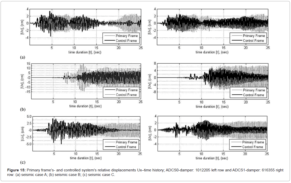
In all seismic loading cases ADCS0 induces an increase of the maximum relative displacements compared to the primary frame’s response, by 42% in seismic case A, 129% in case B and 77% in case C (Table 3). The controlled system’s respective average increase with the optimum hysteretic damper 1012205 amounts to 83%. This proves that the good energy dissipation performance achieved by the controlled system takes place at the cost of increased relative displacements. In the case of ADCS1 for a selected DR value of 114.3 1/m (damper: 616355) the controlled system’s maximum relative displacement reduces almost by 9% for seismic case A and 15% for -case B, although in -case C it increases insignificantly by almost 1% (Table 3). The relative displacements of the controlled system reduce thus on average by almost 8%.
| Seismic Case | Max. Relative displacement [cm] | ||
|---|---|---|---|
| Primary Frame | ADCS0 | ADCS1 | |
| A | 2.561 | 3.625 | 2.336 |
| B | 6.779 | 15.49 | 5.759 |
| C | 2.805 | 4.959 | 2.828 |
Table 3: Primary frame’s- and ADCS relative displacements response.
Figure 15 shows the time-history for the first 25 s of the primary frame’s relative displacements to the controlled systems’ relative displacements for ADCS0 on the left row and ADCS1 on the right row.
Damper’s shear deformations
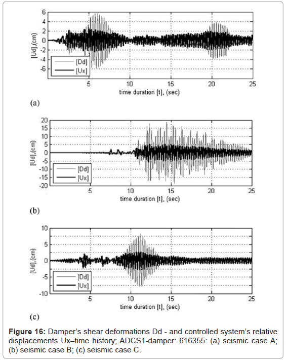
The hysteretic damper is positioned at the horizontal midpoint between the horizontal bracing member and the beam, so that its deformations due to shear action reach maximum values through relative displacements of the primary system to the bracing member attached. The chevron bracing connected to the eccentric disc of the lower horizontal connecting plate of the damper induces further increase of the damper’s shear deformations during the frame motion through its re-centering action. For a DR value of 114.3 1/m (damper: 616355), the maximum shear deformations of the damper account to 5.626 cm for seismic case A, 18.65 cm for case B and 8.109 cm for case C. Compared to the controlled system’s relative displacements the deformation increase of the element amounts to 141, 224 and 187% for the three seismic cases respectively.
Figure 16 shows the time-history for the first 25 s of the damper’s shear deformations for the three loading cases, for a DR value of 114.3 1/m (damper: 616355). The light colored lines represent the damper’s shear deformations and the bright colored lines, the controlled system’s relative displacements.
Bracings axial force
In the selected controlled system the cables were modeled as frame objects with zero compression limit. For avoiding any related modification of the members’ axial forces, these were assigned a suitable pretension stress through a target force. For the range of the developed stresses and strains in the bracing members, the material’s mechanical behavior is assumed to be linear.
The static vertical- and horizontal loading of the frame causes tension only to the bracing, although under seismic loading compression has also been developed in the members. The magnitude of the prestress target force is slightly higher than the maximum resulting force in the bracings when subjected under the selected seismic excitations. In seismic case B a maximum compression force of 107.35 kN was developed in the side diagonal of ADCS1 portal bracing. For preventing this, a prestress of 25% of the maximum allowable stress of fe=40 kN/cm2 was applied by following a trial and error procedure. The prestress force leads to a linear elastic resistance by the bracings in all seismic loading cases (Table 4).
| Seismic Case | Max. Tension force [kN] | ||
|---|---|---|---|
| Horizontal brace | Side braces | Chevron braces | |
| A | 46.23 | 190.37 | 103.22 |
| B | 56.49 | 244.94 | 121.05 |
| C | 42.64 | 173.43 | 98.46 |
Table 4: ADCS1 cables axial forces with 25% prestress (damper: 616355).
Conclusions
In the present study the concept of adaptable dual control systems, ADCS, based on two different bracing configurations, a cross- and a portal- with a chevron cable bracing all formed with closed circuit and a hysteretic damper of steel plates has been introduced. The earthquake responses of the controlled systems have been investigated based on a simplified SDOF-model and three international strong ground motions. ADCS innovative mechanism enables the elastic response of the primary structure and the dissipation of the earthquake induced energy through plastic hysteresis of the dampers. The design configurations of the bracing-damper mechanism lead to a continuous most uniform counteraction of all structural members to resist the earthquake loading, while they practically avoid an interaction on the stiffness of the primary frame. Therefore the application of the control mechanism becomes an attractive alternative, not only for the design of earthquake resistant structures but also for the seismic retrofit of existing ones.
ADCS design considerations are linked to the optimum properties of the bracing-damper mechanism. The optimization design procedure of the proposed bracing-damper mechanism aims at highest possible energy dissipation and prevention of increase in the base shear and relative displacements of the controlled system. The influencing geometrical and mechanical properties of the hysteretic damper were traced through a numerical analysis based on 397 different combinations of design parameters, whereas the Effective Energy Deformation Index, EEDI and the Damper Ratio, DR, were chosen for the evaluation of the control efficiency of ADCS. An optimum range of DR-values has been proposed and evaluated for the specific bracing-damper mechanism proposed in the present paper, in terms of energy dissipation performance, base shear- and relative displacements of the controlled system. In principle, both optimum controlled systems develop similarly high EEDI values under the seismic cases considered. ADCS1 succeeds in high energy dissipation performance without significant alteration of the controlled system’s base shear and relative displacement responses. On the other side, the cross bracing mechanism configuration originally proposed with the introduction of ADCS proved to perform well in terms of energy dissipation, but with increased relative displacements of the controlled system. Further experimental and numerical research on the application of the proposed ADCS-configuration in multistory buildings would address issues among others of optimum damping and stiffness distribution over the height, as well as establish a design methodology for the control mechanism.
References
- Christopoulos C, Filiatrault A (2006) Principle of Passive Supplemental Damping and Seismic Isolation: IUSS Press, University of Pavia, Italy.
- Takewaki I (2009) Building Control with Passive Dampers: Optimal Performance-based Design for Earthquakes, John Wiley & Sons, Asia.
- Hanson, RD, Soong, TT (2001) Seismic Design with Supplemental Energy Dissipation Devices, EERI, Oakland, CA.
- Soon TT, Chichester (1997) Passive Energy Dissipation Systems in Structural Engineering.
- Towashiraporn P, Park J, Goodno BJ, Craig JI (2002) Passive control methods for seismic response modification. Progress in Structural Engineering and Materials 4: 74-86.
- Di Sarno L, Elnashai AS (2005) Innovative strategies for seismic retrofitting of steel and composite structures. Progress in Structural Engineering and Materials 7: 115-135.
- Martelli A, Brebbia CA (2007) Seismic isolation and energy dissipation: worldwide application and perspectives. Earthquake resistant engineering structures VI. WIT Press, Southampton.
- Aydin E, Boduroglub MH, Guney D (2007) Optimal damper distribution for seismic rehabilitation of planar building structures.Engineering Structures 29: 176-185.
- Takewaki I (1997) Optimal damper placement for minimum transfer functions. Earthquake Engineering and Structural Dynamics 26: 1113-1124.
- Uetani K, Tsuji M, Takewaki I (2003) Application of optimum design method to practical building frames with viscous dampers and hysteretic dampers. Engineering Structures 25: 579-592.
- Zhangn RH, Soong TT (1992) Seismic design of viscoelastic dampers for structural applications. Journal of Structural Engineering 118: 1375-1392.
- Inoue K, Kuwahara S (1998) Optimum strength ratio of hysteretic damper. Journal of Earthquake Engineering and Structural Dynamics 27: 577-588.
- Mayes R, Goings C, Naguib W, Harris S, Lovejoi J, et al. (2004) Comparative performance of buckling-restrained braces and moment frames. Proceedings of 13th World Conference on Earthquake Engineering.
- Filiautrault A, Cherry S (1988) Comparative performance of friction damped systems and base isolation systems for earthquake retrofit and aseismic design. Journal of Earthquake Engineering and Structural Dynamics 16: 389-416.
- Wu B, Zhang J, Williams MS, Ou J (2005) Hysteretic behavior of improved Pall-typed frictional dampers. Journal of Engineering Structures 27: 1258-1267.
- Renzi E, Perno S, Pantanella S, Ciampi V (2007) Design, test and analysis of a light-weight dissipative bracing system for seismic protection of structures. Journal of Earthquake Engineering and Structural Dynamics 36: 519-539.
- Kuratan M, DesRoches R, Leon RT (2008) Cable damper bracing for partial seismic rehabilitation. Proceedings of 14th World Conference on Earthquake Engineering, China.
- Phocas MC, Pocanschi A (2003) Steel frames with bracing mechanism and hysteretic dampers. Journal of Earthquake Engineering and Structural Dynamics 32: 811-825.
- Sophocleous T, Phocas MC, Phocas M, Brebbia CA, Komodromos P (2009) Dual Earthquake Resistant Frames. Earthquake Resistant Engineering Structures VII. WIT Press, Southampton.
- Xia C, Hanson RD (1992) Influence of ADAS element parameters on building seismic response. Journal of Structural Engineering 118: 1903-1918.
- Aiken ID, Nims DK, Whittaker AS, Kelly JM (1993) Testing of passive energy dissipation systems. Earthquake Spectra 9: 335-369.
- Tsai KC, Chen HW, Hong CP, Su YF (1993) Design of steel triangular plate energy absorbers for seismic-resistance construction. Earthquake Spectra 9: 505-528.
- Sophocleous T, Phocas MC (2009) Model of Analysis for Earthquake Resistant Dual Systems. Proceedings of 2nd International Conference on Computational Methods in Structural Dynamics and Earthquake Engineering, Rhodes.
- Nakashima M, Saburi K, Tsuji B (1996) Energy input and dissipation behavior of structures with hysteretic dampers. Journal of Earthquake Engineering and Structural Dynamics 25: 483-496.
Citation: Phocas MC, Sophocleous T (2013) Dual System Configuration for Earthquake Safety. J Archit Eng Tech 2: 108. DOI: 10.4172/2168-9717.1000108
Copyright: ©2013 Phocas MC, et al. This is an open-access article distributed under the terms of the Creative Commons Attribution License, which permits unrestricted use, distribution, and reproduction in any medium, provided the original author and source are credited.
Select your language of interest to view the total content in your interested language
Share This Article
Recommended Journals
Open Access Journals
Article Tools
Article Usage
- Total views: 17899
- [From(publication date): 7-2013 - Aug 20, 2025]
- Breakdown by view type
- HTML page views: 13065
- PDF downloads: 4834
