Renewable Energy from Thermal: Electrical Power Generation in Ceramic and Tile Industry
Received: 30-Jun-2018 / Accepted Date: 19-Jul-2018 / Published Date: 25-Jul-2018 DOI: 10.4172/2576-1463.1000212
Keywords: Electricity grid; Inverter; Thermoelectric cooling
Introduction
A review of the development of thermoelectric
Thermoelectric cooling systems have advantages, including compact in size, light in weight, high reliability, no mechanical moving parts, being powered by direct current. Commonly Thermoelectric cooling referred to as cooling technology using thermoelectric coolers no working fluid. Thermoelectric module Consists of a bunch of thermocouples wired electrically in series and thermally in parallel. Thermocouple is made of two different semiconducting thermo elements. Generate thermoelectric cooling effect when voltage in direction applied through the connected junction [1-5].
Direct conversion of heat energy to electrical energy or vice versa called thermoelectric effects. The temperature difference across the thermoelectric effect causes a potential difference. The contrary, this is also true; by applying a voltage to both ends of thermoelectric the temperature difference is created. Applying temperature, in nuclear dimension, gradient causes the moving of charge carriers from warm side to cold side. This effect is used to produce electricity and to calculate the objects temperature. Temperature is very effective in thermoelectric and there is a direct relationship between temperature and applied voltage polarity [6,7].
The main part of the thermoelectric is thermocouple. Thermocouple is a kind of power generators. It consists of two dissimilar metals. As Figure 1 shows, the p-type and n-type semiconductor that is located on a metal plate for series connection. Locate between two ceramic plates [8,9].

Figure 1: Schematic thermoelectric effects.
Quality of thermoelectric depends on parameters such as the type of electrical current applied to the junction the p-type and n-type semiconductor, the temperature of the hot and cold thermal conductivity and electrical heating elements, and thermal resistance of the thermoelectric heat sinking [8-10].
For the design and operation of thermoelectric coolers dynamic character is very important. Here are three important effects of thermoelectric including: Seebeck, Peltier and Thomson [11].
Seebeck effect
The real significance of this work was unknown about a hundred years. After the construction of dissimilar metal system, it replaced with alternative thermal gradient capable of producing much larger semiconductors. Thomas C. Beck, German scientist, did some tests in 1821, the result is an electric current in a circuit made of two dissimilar conductive passess with the conditions of different junction temperature [12].
The potential difference is caused electricity flowing in the circuit. In fact, the Seebeck effect suggests that the thermal gradient in the electrical circuit, causing electrical current pass. Mathematical methods of Seebeck express temperature difference between the two dissimilar metals junction will cause electric propulsion. As in (1) found E is electric propulsion volts, T1-T2 is temperature difference between two metals, and α shows C. Beck differential coefficient or thermoelectric power coefficient between two conductors or semiconductors [12-15].
 (1)
(1)
Peltier effect
Jean Peltier, French physicist and watchmaker, analyzed Seebeck Effect in 1834. Current in a circuit by connecting non-same-sex is attracted and in another attached flow can be discharged on the same circuit. A few years later, William Thompson measured both Seebeck and Peltier effect. But this phenomenon was considered just as an experiment. In 1930, scientists re-examined the old works and this led them to the construction and development of thermoelectric devices [16-20].
Peltier effect is an important phenomenon in the heating and cooling. This work expresses the theme, when an electric current in a circuit, made of two dissimilar conductors’ passes, the heat energy is taken from one connection and the other connection. This causes the first be cooler and the second be warmer. For this reason, the flow creates a thermal gradient which is contrary to Seebeck effect. Seebeck effect on the 2 is specified. QC is cold, QH the heat, β the coefficient of Peltier differential between the two materials A and B in volts, I is current in amperes [17-19].
 (2)
(2)
This effect is used for cooling or heating. For example, the use of Peltier thermoelectric is [20,21]:
• Water extraction: Peltier effect devices used Dehumidifier for the process of taking water from the air.
• Composition: DNA of the effect of thermal cycle used for the construction of DNA.
• Spacecraft: Peltier effect on the space shuttle, to mitigate the effects of sunlight on both sides of the ship. This phenomenon helps to distribute heat because of direct sunlight; one side of the ship to the other side of the sun does not get cooler.
Ceramic Tile Production Process
Overall manufacturing process can be explained in multi-step. Currently in the world there are two methods for manufacturing ceramic tiles. The main difference between these two methods is in the firing and drying tiles [12,14,22].
The first batch of ardent (double firing) is. In this method, then dry in the dryer tiles, tile has a high thermal load is cooked on the grill. The next step is to add the glaze and bake again for re-sent into the furnace. Most manufacturers are enthusiastic approach. The second method ardent single (single firing) is called. The first baking process is eliminated. Stained Glass tile is glazed after drying in the dryer. The next step is to bake furnace.
Process Description Ceramic tile is divided into 10 stages [12-15,22]:
Weighing raw materials
In order to maintain quality, raw materials are carefully weighed. So it is necessary to accurately scale materials may be used.
Ball mill
Ball mill is a type of grinder used to grind and blend materials for use in mineral dressing processes, ceramics and selective laser sintering. A ball mill consists of a hollow cylindrical shell rotating about its axis. The axis of the shell may be either horizontal or at a small angle to the horizontal. It is partially filled with balls. The grinding media is the balls, which may be made of steel, stainless steel, ceramic, or rubber. The inner surface of the cylindrical shell is usually lined with an abrasionresistant material such as manganese steel or rubber. Less wear takes place in rubber lined mills. The length of the mill is approximately equal to its diameter. A device that consists of a cylindrical ball mill within which there are balls. Cylindrical rotated at constant speed by an electric motor and its rotation is due to roll-over bullet on each other. In this process the mixed soil with water inside the mill to be ground due to the collision with bullets.
Spray dryer
A spray dryer takes a liquid stream and separates the solute or suspension as a solid and the solvent into a vapor. The solid is usually collected in a drum or cyclone. The liquid input stream is sprayed through a nozzle into a hot vapor stream and vaporized. Solids form as moisture quickly leaves the droplets. A nozzle is usually used to make the droplets as small as possible, maximizing heat transfer and the rate of water vaporization.
Spray dryer powder produced in factories producing ceramic tile with uniform density, particle size distribution is fixed and used the same moisture. Spry dryer used to prepare the powder to form slurry. Material obtained from the mill slurry accumulated in the tanks. This leads to homogeneity of the slurry and improve the property is plasticity. Tanks had entered the slurry is spray dried. High-pressure piston pumps the slurry into the hot cylindrical chamber spray dryer falls apart. The slurry after colliding with hot air and water vapor specific humidity and grain powder becomes clear. Ambient air and water vapor passes through the silicon and the output dusting spray dried out.
Forming
Pressing using products from the spry dryer converted into granules. When the water content in the pellets is more than 4 percent from the press semi-arid, and in cases where the amount of water in the dry granules is less than 4 percent of the press.
Dryer
After entering pellets into the dryer, the water content of less than one percent and is ready for cooking. In the old days took dryers can be done to this process. But in the new dryers can reduce this time to about 20 minutes is reached.
Engob
Engob cover for covering the enamel used to color granular level. This process begins when the bulk amount of water lost is not yet completely dry.
Glaze
Glaze thin glass layer which covers granular levels caused by melting minerals. Glazed temperature is always lower than the temperature of pellets. Glaze the density, hardness, polished and color of the ceramic. Glazed ceramic objects quite dense and penetration of liquids and gases into the tissue and thus prevents corrosion effect and reduces other adverse factors.
Oven
After the glaze, ceramic stoves for cooking should be. Enamel furnace temperature furnace temperature is less granular. Usually between 1000 to 1040 degrees for about 35 minutes are done.
Grading and classification
Rating: There may be bugs when cooking for glazing ceramics is required before packing them in terms of visual quality rating. Based on the appearance, size and surface are determined. This is done by the operator and the eyes. Operators are based on defects in ceramics to rank them. Categories: Ceramic Then after calibration phase of the transmitted classified.
Packing
At this stage, ceramics are categorized transferred for placement within the carton. Devices for sorting and packaging of ceramics by more arms are placed in a row. Transportation by wind suction is transferred into the input device. Far be labeled cartons. Sharing devices per carton after carton lifted and folded according to the degree laid on a wooden or metal pallets and stretch nylon is wrapped around it with another device has been transferred to the warehouse pallets to be transported from there to the consumer market.
Modeling and Simulation
Thermoelectric generator connected to the ceramic tile factories grid
Today, part of the energy derived from fuel combustion in industry, as heat wasted. Since the temperatures generated by the device is higher than the surrounding environment, the energy contained in them can used for power production. One of the methods of extraction of this energy waste is the use thermoelectric technology. Thermoelectric modules with exposure to ambient air temperature difference between the device and the electrical energy will generate. Ultra long life, lack of moving parts, quiet and relatively low price thermoelectric modules, they are a very attractive option for use in the field.
In recent years, the use of renewable resources is common. The aim of this study was to investigate the feasibility thermoelectric modules for power generation is heating industries. Renewable energy generators can be connected to the distribution grid. In order to connect Thermoelectric Generator system to the grid an inverter is always needed. In Figure 2 Connecting the thermoelectric generator to the Bus grid is shown. Thermoelectric generator is connected to the AC Bus network through the boost converter and inverter [20,21]. Here the inverter is used as a free controller.

Figure 2: Schematic thermoelectric generators connected to grid.
Using the output heat in the production of ceramic tiles
Three systems, as the manufacturing processes for ceramic tiles described, produced a lot of heat. Features of this device can be seen in Table 1. The heat can be used to produce electrical energy. In other words, the loss of heat energy is prevented; recycling can also be prepared and used to generate electrical energy.
| Heat (°C) | Device Name |
|---|---|
| 450-650 | Spray Dryer |
| 300-400 | Ceramic Dryer |
| 1000-1040 | Curing Devices |
Table 1: Profile of heat energy dissipation devices.
Thermoelectric generator module design
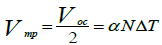
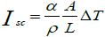
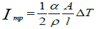
To generate power from thermoelectric, thermoelectric module sets as a layer between the heat source and a heat sink and the temperature difference between the hot and cold causes the electric power generation [23,24]. Math thermoelectric module is shown in the form of 3 to 7 [21]:
 (3)
(3)
 (4)
(4)
 (5)
(5)
 (6)
(6)
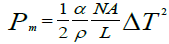 (7)
(7)
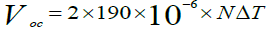
Here the A is the number of Thermocouples, A Thermocouples level, I the temperature difference between the two levels, I current passing through the module, K thickness, K heat transfer coefficient, TH and TH thermoelectric hot and cold surface temperatures, Pm maximum power output, Isc short-circuit current, and Voc is open circuit voltage of the thermoelectric are.
Among the existing thermoelectric with high power, it can be referred to thermoelectric Bismuth Telluride Bi2Te2 [25-27]. Most thermoelectric Volatility factor is between 20 and 300°C. Thermoelectric properties of bismuth are given in Table 2.
| Parameter | Value |
|---|---|
| Seebeck coefficient |  |
| Thermal resistance |  |
| Electrical resistance |  |
Table 2: Values Thermoelectric Bi2Te2.
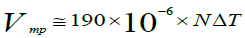
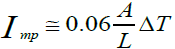
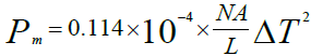
Using the values from Table 2, and placement of voltage, current and power relations will be achieved 8 to 11 [28-30].
 (8)
(8)
 (9)
(9)
 (10)
(10)
 (11)
(11)
As of 9 is specified, and no matter how small inversely larger. But actually such a situation does not occur on very small length. Power and efficiency in real-mode equations 12 and 13 are the ties [31-33].
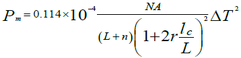 (12)
(12)
 (13)
(13)
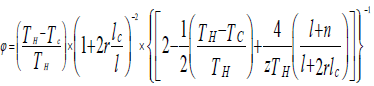
In equation (13) has shown, efficiency, insulation thickness, coefficient advantage, the contact thermal conductivity and electrical resistivity ratio is [25,26,34]. Here the thermoelectric model is used which its specification is specified in Table 3 [35].
| Parameter | Value |
|---|---|
| Leg length, (L) | 0.125 cm |
| Leg area, (A) | 0.0196 cm2 |
| Couples, (N) | 127 |
| Insulation, Thickness (IC) | 0.8 mm |
| Advantage, Factor (z= I/°C) | 0.003 |
| Thermal conductivity contact, (r) | 0.2 I/°C |
| Contact electrical resistance, (n) | 0.1 mm |
Table 3: Profile Thermoelectric TEP 1-12708.
The model thermoelectric connection
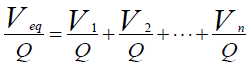
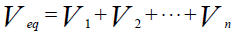
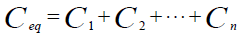
At this stage thermoelectric connection is mentioned. When heat is applied to the thermoelectric energy is produced around it. So you can imagine it like an ideal capacitor and capacitor equations can be applied to it. Here V capacitor according to the farad, V saved by Kelvin and V is the potential difference [10,36,37]. Thermoelectric series circuit equations shown in Equation 14:
 (14)
(14)


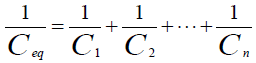
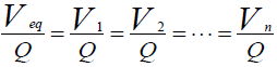
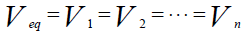
For thermoelectric parallel connection, capacitors in parallel relationship are used are shown in 15 equation [10,36,37].
 (15)
(15)
Boost converter and controller
Boost converter steps up the input voltage magnitude to a required output voltage magnitude without the use of a transformer. The boost converter increases the amplitude of the input voltage to a required output voltage value without the use of a transformer. Has been formed boost converter are an inductor, a diode and a high frequency switch. This coordination manner supply power to the load at a voltage greater than the input voltage magnitude. Method control lies in the manipulation of the duty cycle of the switch which causes the voltage change [38].
There are two modes of operation for the boost converter, for the opening and closing of the switch. The first mode when the switch is closed, the operation is known as the state of charge. The second mode when the switch is open, this practice is known as a discharged state [38].
In Charging Mode, switch is closed and the inductor is charged by the source through the switch. The charging current is exponential in nature, but for simplicity is assumed to be linearly varying [38]. The diode restricts the flow of current from the source to the load. Demand of the load is met by the discharging of the capacitor.
In Discharging Mode the switch is open and the diode is forward biased [38]. The inductor now discharges and together with the source charges the capacitor and meets the load demands. Times change is very small and in many cases is assumed to be constant during operation.
A voltage boost converter DC/DC, for thermoelectric generating, is intended as reinforcement. Capacitors are used between boost converter and a thermoelectric generator reduce harmonics in the high frequency of the. Here α is work cycles between 0 and 1, TS Duration of a switching cycle when IGBT is attached, and inductor and capacitor voltage for open and closed circuit mode for ties 16 and 17 are [10,36-40].
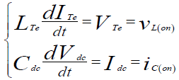 (16)
(16)
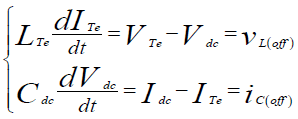 (17)
(17)
Here utilization of a boost converter for control of thermoelectric power using Maximum Power Point Tracking (MPPT) control mechanism is presented. Thermoelectric module is analyzed using SIMULINK software. The main objective of boost converter is to be used along with a MPPT control mechanism. The MPPT is responsible for extracting the maximum possible power from the Thermoelectric. Feed it to the load via the boost converter which steps up the voltage to required magnitude [39].
In order to increase the efficiency of thermoelectric modules, methods are to be undertaken to match the source and load properly. One such method is the Maximum Power Point Tracking (MPPT), used to obtain the maximum possible power from a varying source. The boost converter is used to get the maximum power. Methods used for maximum power point tracking a few are listed below [40]:
• Perturb and Observe method
• Incremental Conductance method
• Parasitic Capacitance method
• Constant Voltage method
• Constant Current method
Perturb and Observe methods is the most common. The two methods very less number of sensors are utilized [22].
Inverter connected grid
After connecting thermoelectric generator it is connected to the boost converter by the inverter. The filter type is used in the inverter is a kind of low pass and set by network voltage. In order to reduce high-order harmonics of the filter PWM modulation is used in the inverter. Inverter controller is designed for voltages of 400 volts. Active and reactive power inverter 18 is as follows [41-45].
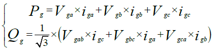 (18)
(18)
Where Vga, Vgb and Vgc three-phase voltage and iga, igb and igc current are injected AC Bus. With 13 ties will become a park.
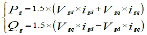 (19)
(19)
That Vgq and Vgd represents voltage components and connection points, Igq and Igd reflects the current components are in line. In the frame of reference Vgd = Vg and Vgq = 0 synchronized with the grid voltage, so be 20 relationships have been obtained.
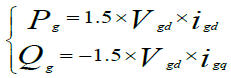 (20)
(20)
Equation three-phase voltage inverter is in the AC form of 21. That filters inductance Lf and Rf resistance..
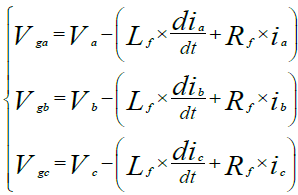 (21)
(21)
Park into equations by applying a voltage three-phase electrical model of the network with axes q and d appear to be between 22 shown.
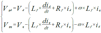 (22)
(22)
Here P frequency and flow control using the P regulator 23 is described in [41-45].
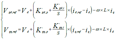 (23)
(23)
Simulation Results
With regard to the relations mentioned in the thermoelectric, usable output power generated from devices heat, spry dryer, drying ovens, have been studied. All devices information that generates heat has been displayed in Table 1. The average temperature is between 400 to 1000°C. Thermoelectric characteristics are also specified in Table 2 and tolerate temperatures for this electricity generator has been defined between 20 and 300 [46-55]. As indicated in Figure 2 simulation, the output of the first three producers of heat energy enters to the chamber until be set to the usable temperature. Then, it is transferred to the thermoelectric generator. The use of electrical energy generated by the boost DC/ DC converter is to strengthen the electrical energy produced by the thermoelectric generator. Energy amplified by the boost converter is delivered to the inverter to convert the AC voltage. The inverter output is connected to the network. The inverter output is connected to the network. Finally, resistance, inductance and capacitance in the circuit Bus DC for C= 200 × 10-3 F, L=0.02H, R=5Ω and Bus AC: F=50 HZ, V = 400V Are. At 300°C, thermoelectric able to produce about 14 watts of electrical power and voltage is 8V [53,60]. Thermoelectric generation is connected in series and parallel connections and 14 and 15 equations. In accordance with these relationships in output, the voltage of 60 volts and 6 Amps will flow. The project was carried out by MATLAB simulation software. Three-phase voltage connected to the bus AC in Figure 3, the three-phase current connected to the bus AC is shown in Figure 4. Figure 5 shows the output power of the Inverter. Figures 6 and 7 shows the boost converter is controlled.

Figure 3: Three-phase voltage inverter output in the bass.

Figure 4: Three-phase current inverter output in the bass.

Figure 5: Power output inverter the bass.

Figure 6: The reference voltage controller boost.

Figure 7: Fashion index current controller.
Discussion and Conclusion
As it is clear in Figure 1, the ceramic tile production in the factory was shown. In this cycle, there are devices such as: Spry dryer, dryer, and furnace that produce much heat. In other words, the produced heat energy is wasted. This study aimed to replace fossil fuels with renewable energy and optimizing fuel consumption by increasing the efficiency of the process. The aim of this research is to prevent losing of heat energy and change it to electrical energy. In fact, the thermal energy will efficiently be used. The recovery method of wasted heat energy is to use thermoelectric generator. Thermoelectric is used to produce electric energy in car [16-19]. Moreover, it is used to produce thermoelectric train [35]. Production of electrical energy to heat energy that high heat can used in Industries such as factories glass, cement and steel could be used [56-59].
• The advantages of this study are formulated as follows:
• This generator can be connected to the distribution network and transfers electrical energy to network.
• The recovery of thermal energy helps optimally use of it.
• Using of available space and available equipment without changing the working process.
• The method of electrical energy production from heat energy can be used in industries such as glass, cement and steel factories.
• Ultra long life, lack of moving parts, quiet and relatively low price thermoelectric modules, they are a very attractive option for use in the field.
• Using the DG of environmental pollution cut.
References
- Zhao D, Tan G (2014) A review of thermoelectric cooling: materials, modeling and applications. Appl Therm Eng 66: 15-24.
- Omid M, Kianifar A, Kalogirou SA, Pop I, Wongwises S (2013) A review of the applications of nanofluids in solar energy. Int J Heat Mass Transfer 57: 582-594.
- Gao HB, Huang GH, Li HJ, Qu ZG, Zhang YJ (2016) Development of stove-powered thermoelectric generators: A review. Appl Therm Eng 96: 297-310.
- Fitriani, Ovik R, Long BD, Barma MC, Riaz M, et al. (2016) A review on nanostructures of high-temperature thermoelectric materials for waste heat recovery. Renew Sust Energ Rev 64: 635-659.
- Riffat SB, Ma X (2004) Improving the coefficient of performance of thermoelectric cooling systems: a review. Int J Energy Res 28: 753-768.
- Lineykin S, Ben-Yaakov S (2007) Modeling and analysis of thermoelectric modules. IEEE Transactions on Industry Applications 43: 505-512.
- Escriba C, Campo E, Esteve D, Fourniols JY (2005) Complete analytical modeling and analysis of micromachined thermoelectric uncooled IR sensors. Sensors and Actuators A: Physical 120: 267-276.
- Riffat SB, Ma X (2003) Thermoelectrics: a review of present and potential applications. Appl Therm Eng 23: 913-935.
- Tassou SA, Lewis JS, Ge YT, Hadawey A, Chaer I (2010) A review of emerging technologies for food refrigeration applications. Appl Therm Eng 30: 263-276.
- Zamiri E, Vosoughi N, Hosseini SH, Barzegarkhoo R, Sabahi M (2016) A New Cascaded Switched-Capacitor Multilevel Inverter Based on Improved Series–Parallel Conversion With Less Number of Components. IEEE Transactions on Industrial Electronics 63: 3582-3594.
- Flor ML, Oltra MJ (2004) Identification of innovating firms through technological innovation indicators: an application to the Spanish ceramic tile industry. Research Policy 33: 323-336.
- Pang H, Piao YY, Tang YQ, Jiang GY, Wang JH, et al. (2013) Thermoelectric behaviour of segregated conductive polymer composites with hybrid fillers of carbon nanotube and bismuth telluride. Mater Lett 107: 150-153.
- Pei ZJ, Fisher GR, Liu J (2008) Grinding of silicon wafers: a review from historical perspectives. Int J Mach Tool Manu 48: 1297-1307.
- Chen JC, Wey MY, Chiang BC, Hseih SM (1998) The simulation of hexavalent chromium formation under various incineration conditions. Chemosphere 36: 1553-1564.
- Antar Z, Feller JF, Noel H, Glouannec P, Elleuch K (2012) Thermoelectric behaviour of melt processed carbon nanotube/graphite/poly (lactic acid) conductive biopolymer nanocomposites (CPC). Mater Lett 67: 210-214.
- Wang EH, Zhang HG, Fan BY, Ouyang MG, Zhao Y, et al. (2011) Study of working fluid selection of Organic Rankine Cycle (ORC) for engine waste heat recovery. Energy 36: 3406-3418.
- He W, Zhang G, Zhang X, Ji J, Li G, et al. (2015) Recent development and application of thermoelectric generator and cooler. Appl Ener 143: 1-25.
- Xi H, Luo L, Fraisse G (2007) Development and applications of solar-based thermoelectric technologies. Renew Sust Energ Rev 11: 923-936.
- Liu ZB, Zhang L, Gong G, Han T (2015) Experimental evaluation of an active solar thermoelectric radiant wall system. Energy Convers Manage 94: 253-260.
- Bai S, Lu H, Wu T, Yin X, Shi X, et al. (2014) Numerical and experimental analysis for exhaust heat exchangers in automobile thermoelectric generators. Case Studies in Thermal Engineering 4: 99-112.
- Wang Y, Dai C, Wang S (2013) Theoretical analysis of a thermoelectric generator using exhaust gas of vehicles as heat source. Appl Ener 112: 1171-1180.
- Berrera M, Dolara A, Faranda R, Leva S (2009) Experimental test of seven widely-adopted MPPT algorithms. Power Tech, 2009 IEEE Bucharest. IEEE.
- Wang XD, Huang YX, Cheng CH, Lin DT, Kang CH (2012) A three-dimensional numerical modeling of thermoelectric device with consideration of coupling of temperature field and electric potential field. Energy 47: 488-497.
- Chen WH, Wang CC, Hung CI, Yang CC, Juang RC (2014) Modeling and simulation for the design of thermal-concentrated solar thermoelectric generator. Energy 64: 287-297.
- Meng JH, Wang XD, Zhang XX (2013) Transient modeling and dynamic characteristics of thermoelectric cooler. Appl ener 108: 340-348.
- Meng JH, Zhang XX, Wang XD (2014) Dynamic response characteristics of thermoelectric generator predicted by a three-dimensional heat-electricity coupled model. J Power Sources 245: 262-269.
- Ismail B, Ahmed W (2009) Thermoelectric power generation using waste-heat energy as an alternative green technology. Recent Patents on Electrical & Electronic Engineering 2: 27-39.
- Ali SA, Mazumder S (2013) Computational study of transverse Peltier coolers for low temperature applications. Int J Heat Mass Transf 62: 373-381.
- Joshi JV, Patel NM (2012) Thermoelectric system to generate electricity from waste heat of the flue gases. Adv Appl Sci Res 3: 1077-1084.
- Hsiao YY, Chang WC, Chen SL (2010) A mathematic model of thermoelectric module with applications on waste heat recovery from automobile engine. Energy 35: 1447-1454.
- Feeley TJ, Skone TJ, Stiegel GJ, McNemar A, Nemeth M, et al. (2008) Water: A critical resource in the thermoelectric power industry. Energy 33: 1-11.
- Mata TM, Martins AA, Caetano NS (2010) Microalgae for biodiesel production and other applications: a review. Renew Sust Energ Rev 14: 217-232.
- Snyder JG (2003) Design and optimization of compatible, segmented thermoelectric generators. 22nd International Conference on Thermoelectrics.
- Xiao J, Yang T, Li P, Zhai P, Zhang Q (2012) Thermal design and management for performance optimization of solar thermoelectric generator. Appl Ener 93: 33-38.
- MartÃn-Márquez J, Rincón JM, Romero M (2008) Effect of firing temperature on sintering of porcelain stoneware tiles. Ceramics International 34: 1867-1873.
- Liu J, Cheng KWE, Ye Y (2014) A cascaded multilevel inverter based on switched-capacitor for high-frequency AC power distribution system. IEEE Transactions on Power Electronics 29: 4219-4230.
- Hinago Y, Koizumi H (2012) A switched-capacitor inverter using series/parallel conversion with inductive load. IEEE Transactions on Industrial Electronics 59: 878-887.
- Sanchis P, Ursaea A, Gubia E, Marroyo L (2005) Boost DC-AC inverter: a new control strategy. IEEE Transactions on power electronics 20: 343-353.
- Mummadi V (2011) Control of TI-SEPIC converter for optimal utilization of PV power. India International Conference on Power Electronics 2010 (IICPE2010).
- Esram T, Chapman PL (2007) Comparison of photovoltaic array maximum power point tracking techniques. IEEE Transactions on energy conversion 22: 439-449.
- Zaki AM, Amer SI, Mostafa M (2012) Maximum power point tracking for PV system using advanced neural networks technique. Int J Emerg TechnolAdv Eng 2: 58-63.
- Salas V, OlÃas E, Barrado A, Lázaro A (2006) Review of the maximum power point tracking algorithms for stand-alone photovoltaic systems. Sol Energy Mater Sol Cells 90: 1555-1578.
- Reisi AR, Moradi MH, Jamasb S (2013) Classification and comparison of maximum power point tracking techniques for photovoltaic system: A review. Renew Sust Energ Rev 19: 433-443.
- Jung HC, Krumdieck S, Vranjes T (2014) Feasibility assessment of refinery waste heat-to-power conversion using an organic Rankine cycle. Energy Convers Manag 77: 396-407.
- Junye H, Yaping C, Jiafeng W (2014) Thermal performance of a modified ammonia–water power cycle for reclaiming mid/low-grade waste heat. Energy Convers Manag 85: 453-459.
- Chen M, Rosendahl LA, Condra T (2011) A three-dimensional numerical model of thermoelectric generators in fluid power systems. Int J Heat Mass Transfer 54: 345-355.
- Hsu CT, Huang GY, Chu HS, Yu B, Yao DJ (2011) Experiments and simulations on low-temperature waste heat harvesting system by thermoelectric power generators. Appl Ener 88: 1291-1297.
- Wang CC, Hung CI, Chen WH (2012) Design of heat sink for improving the performance of thermoelectric generator using two-stage optimization. Energy 39: 236-245.
- Chen M, Lund H, Rosendahl LA, Condra TJ (2010) Energy efficiency analysis and impact evaluation of the application of thermoelectric power cycle to today’s CHP systems. Appl Ener 87: 1231-1238.
- Wang L, Jia X, Wang D, Zhu G, Li J (2013) Preparation and thermoelectric properties of polythiophene/multiwalled carbon nanotube composites. Synthetic Metals 181: 79-85.
- Liebscher M, Gartner T, Tzounis L, Micusik M, Potschke P, et al. (2014) Influence of the MWCNT surface functionalization on the thermoelectric properties of melt-mixed polycarbonate composites. Compos Sci Technol 101: 133-138.
- Wang D, Su Y, Chen D, Wang L, Xiang X, et al. (2015) Preparation and characterization of poly (3-octylthiophene)/carbon fiber thermoelectric composite materials. Composites Part B: Engineering 69: 467-471.
- Li J, Lai C, Jia X, Wang L, Xiang X, et al. (2015) Effect of electron donor/acceptor substituents on the Seebeck coefficient and thermoelectric properties of poly (3-methylthiophene methine) s/graphite composites. Composites Part B: Engineering 77: 248-256.
- Li L, Chen X, Qi S (2016) Preparation and microwave absorbing property of Ni–Zn ferrite-coated hollow glass microspheres with polythiophene. ‎J Magn Magn Mater 417: 349-354.
- Kraemer D, Poudel B, Feng HP, Caylor JC, Yu B, et al. (2011) High-performance flat-panel solar thermoelectric generators with high thermal concentration. Nat Mater 10: 532-538.
- Hadjistassou C, Kyriakides E, Georgiou J (2013) Designing high efficiency segmented thermoelectric generators. Energy Convers Manage 66: 165-172.
- Tian H, Sun XX, Jia Q, Liang X, Shu G, et al. (2015) Comparison and parameter optimization of a segmented thermoelectric generator by using the high temperature exhaust of a diesel engine. Energy 84: 121-130.
- Kalinowski P, Hwang Y, Radermacher R, Hashimi RA, Rodgers P (2009) Application of waste heat powered absorption refrigeration system to the LNG recovery process. Int J Refrig 32: 687-694.
- Ma M, Yu J (2014) An analysis on a two-stage cascade thermoelectric cooler for electronics cooling applications. Int J Refrig 38: 352-357.
Citation: Mohammadi AM (2018) Renewable Energy from Thermal: Electrical Power Generation in Ceramic and Tile Industry. Innov Ener Res 7:212. DOI: 10.4172/2576-1463.1000212
Copyright: © 2018 Mohammadi AM. This is an open-access article distributed under the terms of the Creative Commons Attribution License, which permits unrestricted use, distribution, and reproduction in any medium, provided the original author and source are credited.
Select your language of interest to view the total content in your interested language
Share This Article
Recommended Journals
Open Access Journals
Article Tools
Article Usage
- Total views: 7091
- [From(publication date): 0-2018 - Dec 22, 2025]
- Breakdown by view type
- HTML page views: 6028
- PDF downloads: 1063