Simultaneous Effects of Soil-structure and Masonry Infill-Structure Interactions on Seismic Performance of Steel Frames
Received: 18-May-2017 / Accepted Date: 23-May-2017 / Published Date: 30-May-2017 DOI: 10.4172/2168-9717.1000197
Abstract
In this paper, the effects of dynamic Soil-Structure Interaction (SSI) on seismic performance of steel frames with infill wall were investigated. This study assesses these buildings seismic performance utilizing the static analysis of nonlinear simulated models to obtain the structures response. The investigation was based on structures with design and detailing characteristics representative of 2800 Iranian code. To consider the dynamic soil-structure interaction effect, soil can be modeled with a set of springs and dashpots. The results show soil-structure interaction and presence of infill wall in building can be able to change the seismic performance of frame structures. Dynamic soil-structure interaction increases system flexibility. Increasing the number of column spans in all cases of loading, increases the amount of the base shear and story drift. The analysis results, also, show that reducing the shear wave velocity in soil beneath the structure, causes soil-structure interaction effects on nonlinear structural response become significant.
Keywords: Steel frame, Infill panel, Soil-structure interaction, Seismic performance
77022Introduction
Various reasons such as random input data, complexity of the structure system, dynamic and nonlinearity of the problem lead to difficulty of dynamic analysis of the structures under the seismic excitations. Main step in performance based seismic design is estimating the nonlinear seismic response of the structures. There are two methods for this aim; nonlinear time history analysis and usual nonlinear static analysis. Nonlinear dynamic analysis has some complexity hence to study the performance of the structures using the nonlinear statically analysis is reasonable. Aim of this investigation is determining the structure performance by evaluating the displacement demand and structure resistant under design earthquake and then comparing these demands with available capacity at target performance level. At viewpoint of resistance parameter, neglecting the effect of infill walls is conservative; these walls have positive effect on structure overall stability and earthquake force resistance, by increasing the frame resistance. But neglecting the effect of these walls is not conservative always. In fact infill wall transfers high force which leads to fracturing the infill wall and transferring the force to the column after initial cycles. This sudden force transformation causes failure of the columns and then collapse of the structure, since the model frame without infill wall has lower strength and it is designed for lower level of force. In attention to the researches which were performed by Geol and Chopra, in fact presence of these elements causes structure becomes more rigid and period of the structure reduces [1-3]. Hence the infill walls should not neglected in analysis and design stages. The idea of using the equivalent rod instead the masonry infill wall was proposed by Polyakov at 1960 for first time. Then Mainstone [4], Stafford Smith [5], Madan [6] proposed the methods to represent the infill wall equivalent rod. Saneinejad and Hobbs [7] presented the new method to analyze the steel composite frames with brick or concrete infill wall against the in plane load.
If soil damping is totally eliminated and soil is only considered as spring we confront with worst status [8]. In the other word maximum seismic response produces. Approaching this method, Muller [9] solved two cases of soil with and without damping. In Rodriguez and Montes [8] studies equivalent damping was considered as minimum value and equal to structure damping 0.5% which was conservative choice. Results lie on the soft and rigid base ranges, so with this assumption the effect of dynamic soil-structure interaction in flexible mode is higher than the nonflexible mode. Importance of the soil-structure interaction effects for the flexible and nonflexible cases were represented in Aviles and Perez-Rocha [10] investigations; they also presented a method which was applicable. Ghannad and Ahmadnia [1] investigations base was solving the soil-structure system which structure was elasto-plastic and soil was modeled by cone model. Interaction effect on inelastic structures was investigated as detailed. They mentioned that despite soil-structure interaction has beneficial effect on structures with high period, eliminating the interaction effect for structure that has period which is lower than the predominant period leads to non conservative response. It is especially more important for structures which are founded on soft soil that has higher value of site period. It was also observed that the interaction effect has less importance on structures which their displacements are in inelastic range.
It is mentioned that proposition which was based on the equivalent linear was presented by Ghannad and bayat [11]. Finally the comparison was performed between the proposed method and response of FEMA 440 method [12]. As it is mentioned previously inelastic soil-structure system can be replaced with the equivalent rigid base system with equivalent period-damping and equivalent plasticity. Regard to linear equalization method of equivalent damping, it was mentioned that above description did not produce advances in solving the nonlinear systems. This description, only, got more accurate response in compare to FEMA 440 in some ranges.
In attention to above and this fact that simultaneously effect of infill wall and dynamic soil-structure interaction on structure was not studied yet, these effects are investigated in this paper.
Soil modeling in soil-structure interaction analysis most significant problem in soil-structure interaction (SSI) analysis is representation of suitable soil model. There are several methods with various complexity and accuracy to investigate the dynamic soil-structure interaction during the earthquake. When aim is the layered soil modeling, following methods can be used [13]:
Considering the soil as equivalent mass, spring and dashpot at the base of structure
Using the equivalent spring and dashpot which are applied at the base of the structure is the simplest method to model the soil. In this method the spring stiffness and damping are calculated for each degree of freedom and are applied at the interface of the structure and base.
Considering the soil as shear beam with continuous or concentrated mass and distributed stiffness
When soil contains various layers it is better that soil is modeled using the shear beam method with concentrated mass, spring and dashpot [14]. Above model can be used to model the dynamic behavior of layered soils which are lied on the bedrock. Since in this method shear wave theory was used, this method was called as shear beam.
Soil simulates as finite element model
In some cases when soil is stratified horizontally or vertically and it is necessary to study the soil nonlinear behavior in interaction analysis, the elastic half space model cannot be used thus finite element model should be applied.
In this paper soil-structure interaction problem was investigated using the substructure method and soil effect was considered by equivalent spring and dashpot. To evaluate the springs stiffness which are located at the soil interface and to count the damping coefficient of dashpot Wolf [15] proposition which are represented in Table 1, was used.
| Mode | Spring stiffness | γ0 | Damping | |
|---|---|---|---|---|
| Vertical |  |
0.58 |  |
|
| Horizontal |  |
0.85 | ||
| Rocking |  |
 |
Table 1: Stiffness and damping after wolf (1985).
Masonry infill wall: If the masonry wall without infill is subjected to the diagonal loading, usually it fractures suddenly. This breaking begins from the stepped crack which is generated in diagonal direction of loading and then panel is divided to two separated regions. Thus wall will collapse because it is not restricted.
The elastic stiffness of a panel of unreinforced masonry infill before cracking should be calculated by applying the equivalent compression diagonal strut with width of a according to eqn. (1) [16].
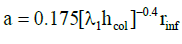 (1)
(1)
Where:
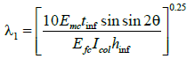 (2)
(2)
In eqn. (2) hcol, is altitude from the column centre (cm), hinf, is the height of infill panel (cm), Efe, is expected elastic modulus of frame material (cm2/kg), Emc, is expected elastic modulus of infill material, Icol, is inertia moment of column (cm4), rinf, is dimension of infill panel diameter (cm) which it equals to  is thickness of infill panel and equivalent compression strut (cm), θ, equals to
  , in which hinf is infill height and Linf is infill length and λ1, is the coefficient which is used to calculate the equivalent compression strut.
Expected shear strength of infill wall, Vint, is calculated by eqn. (3):
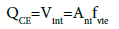 (3)
(3)
Where Ani, is the net horizontal sectional area of mortar between two adjacent row of infill panel and fvie, is the expected shear strength of infill (Figure 1).

Figure 1: Equivalent rod model in infill wall.
Analysis and Loading
Properties of investigated structure models: In this research, 6 structural models with 3, 8 and 15 stories and 3 and 6 spans were selected to represent the short, mean and tall buildings which were located at the area with high seismic risk according to Figure 2. It was endeavored that selected structures match with the real building constructions criteria in the big cities.

Figure 2: Investigated structures.
Mentioned frames were modeled in SAP2000. First it was supposed that frames with and without infill wall were located on rigid support and then the effect of dynamic soil-structure interaction on structure with infill wall was investigated. Structures which were investigated in this research were located in Tehran. These building were loaded according to the sixth topic of Iranian uniform building code and were subjected to the critical gravitational loading Load=0.9QD(Load1=0.9QD and Load2=1.1(QD+QL)). They were also subjected to triangular and uniform form of lateral loading according to Iranian seismic design code No.2800 and AISC-ACD89. Structures were loaded seismically using the spectral analysis and applying the standard design spectra with design fundamental acceleration of A=0.35 for area with high seismic risk and earthquake risk level of 1 and then were analyzed for life safety performance level.
Structure was constructed with steel beams and columns according to Stahibua-Profile table.
Properties of soil which supports the structure: The soil characteristics which were used to study the effect of dynamic soilstructure interaction are tabulated in Table 2.
| Type of the ground | Shear wave velocity | Description of the ground | (KN/m3) | v | G0 (N.m2) |
|---|---|---|---|---|---|
| III | 275 | Weathered rocks and medium dense soils | 18 | 0.4 | 136125000 |
| IV | 150 | Soft deposits with high wet because of raised ground water table | 18 | 0.4 | 38250000 |
Table 2: Soil properties according to Iranian seismic design code No. 2800 [17].
The soil system was divided to desired elements using the stiffness relation and then stiffness coefficients were calculated for middle and end nods. These coefficients are represented in Tables 2 and 3 [17].
| Characteristic | Name of Model | KX | KX | Kγ | Kγ |
|---|---|---|---|---|---|
| End Nod Horizontal Rigidity | Mid Nod Horizontal Rigidity | End Nod Vertical Rigidity | Mid Nod Vertical Rigidity | ||
| III-3stories with 3spans | 17714 | 35428 | 35428 | 70856 | |
| III-8stories with 3spans | 17714 | 35428 | 35428 | 70856 | |
| III-15storie with 3spans | 17714 | 35428 | 35428 | 70856 | |
| III-3tories with 6 spans | 12796 | 25592 | 25592 | 51184 | |
| III-8stories with 6spans | 12796 | 25592 | 25592 | 51184 | |
| III-15storie with 6spans | 12796 | 25592 | 25592 | 51184 | |
| IV-3stories with 3spans | 4977 | 9955 | 9955 | 19910 | |
| IV-8stories with 3spans | 4977 | 9955 | 9955 | 19910 | |
| IV-15storie with 3spans | 4977 | 9955 | 9955 | 19910 | |
| IV-3tories with 6 spans | 3596 | 7192 | 7192 | 14382 | |
| IV-8stories with 6spans | 3596 | 7192 | 7192 | 14382 | |
| IV-15storie with 6spans | 3596 | 7192 | 7192 | 14382 | |
Table 3: Stiffness and damping coefficients of total.
Properties of infill walls which were used in building: Unreinforced masonry infill before cracking can be tacked into account by using the equivalent compression diagonal strut with width of a. Thicknesses of infill and equivalent compression strut and also displacement and lateral strength between the respected infill walls were calculated which are shown in Table 4.
| Name of Model | 3 stories structure with 3 and 6 spans | 8 stories structure with 3 and 6 spans | 15 stories structure with 3 and 6 spans | |
|---|---|---|---|---|
| tinf | Thickness of infill panel (cm) | 30 | 30 | 30 |
| t3 | Thickness of equivalent rod (cm) | 12.4 | 12.86 | 17.91 |
| Q | Lateral strength (Kg) | 23226 | 22251 | 21957 |
| D | Displacement (cm) | 1.4 | 1.28 | 1.08 |
Table 4: Dimensions of equivalent rod.
Results
Investigations of stories lateral displacements and drifts
Drift of each story is the difference between the displacements of mass centers at the top and bottom of the story. This displacement is usually calculated for design earthquake or earthquake performance level. The concept of story drift is used to control the lateral displacements. Using this concept, story drift is calculated at performance level then it is compared with limit values; these values are only used to qualitative evaluation of the structure behavior at desired performance level. To sentence that neglecting the effect of soil-structure interaction is conservative or not, it is necessary to investigate the stories drift. So that controlling the drift could has an important and determinative role in selection of sections properties. Also increasing the maximum lateral displacements of stories in tall slender building can aggravate the P-Δ effect [18-23].
Initially, the displacement at performance level of structure at a point which is located on roof is accounted and then displacements of corresponded points in other stories are also calculated. Finally the stories drift at performance levels for various loading are evaluated. Values of stories drifts and lateral displacements for cases of structure with infill wall, with and without SSI effect (soil type 3 and 4) are shown in Figures 3-14. These figures are results of nonlinear static analysis.

Figure 3: (A-D) Drift of 3 stories building with 3 spans.

Figure 4: (A-D) Drift of 3 stories building with 6 spans.

Figure 5: (A-D) Drift of 8 stories building with 3 spans.

Figure 6: (A-D) Drift of 8 stories building with 6 spans.

Figure 7: (A-D) Drift of 15 stories building with 3 spans.

Figure 8: (A-D) Drift of 15 stories building with 6 spans.

Figure 9: (A-D) Story lateral displacement of 3 stories building with 3 spans in target displacement.

Figure 10: (A-D) Story lateral displacement of 3 stories building with 6 spans in target displacement.

Figure 11: (A-D) Story lateral displacement of 8 stories building with 3 spans in target displacement.

Figure 12: (A-D) Story lateral displacement of 8 stories building with 6 spans in target displacement.

Figure 13: (A-D) Story lateral displacement of 15 stories building with 3 spans in target displacement.

Figure 14: (A-D) Story lateral displacement of 15 stories building with 6 spans in target displacement.
Stories drift for each structure for various loading are depicted on one graph to better investigation of stories drifts. In attention to investigated models, it can be seen that the ratio of displacement with SSI effect to those without SSI effect, has a value less than one. This has not safe tolerance in attention to the reduction of lateral shear due to SSI. To seismic design of structure with more than 8 stories considering the soil-structure interaction in ground type 3 seems to be necessary. Omitting the short structures in which soil-structure interaction causes reduction of shear and lateral displacements in 5 and 8 stories models there are significant increases of lateral displacement. Despite reducing the shear ratio of sorties in 5 and 8 stories models, it is not possible to assess the capability of sections exactly. So that considering the soilstructure effect to exact and optimized design of these structures seems to be necessary. The multiple increment of maximum displacements and drifts of stories due to soil-structure interaction effect is apparent.
The lateral displacement due to SSI effect increases because of two fallowing reasons
1) Presence of soil as a flexible system in analysis causes the fundamental period of structure in compare to fixed base increases and softening the underlying soil, this increasing of fundamental period becomes ascendance.
2) Results of the experimental analyses of soil-structure interaction showed that in short structures horizontal and rocking motions contribute identically in structure vertex response. But in high rise building increasing the height, rocking motion contribution increases and horizontal motion contribution reduces. So that displacements of structure stories are governed by rocking motion in which softening the underlying soil the contribution of rocking motion increases as ascendant. As a result of this contribution increasing, as it was mentioned already in case of more than 8 stories buildings which are founded on ground type 3 and the case of more than 3 stories buildings which are founded on ground type 4 (softer soil), displacements for condition with soil-structure interaction in compare to no SSI effect increases significantly.
Generally due to soil-structure interaction seismic forces (lateral force or base shear) reduce and lateral displacements increase. Considering the soil-structure effect in analysis of more than 3 stories building causes reduction of base shear and increment the lateral displacement of structure. It can be deduced that increasing the number of spans, time period of calculation increments. Cause of these changes is reduction of infill wall stiffness in frames with large number of spans; increasing the numbers of spans, infill wall rigidity decreases.
Force which was applied to shear base
In attention to Figure 15, the values of base shear ratio for cases with infill wall with and without soil-structure interaction for each model was investigated and it is seen that base shear in short 3 stories 3 and 6 spans structures has a negligible increase for soil type 4 in compare to soil type 3. In the 15 stories 3 spans structures increasing the height under both gravitational and triangular loading combinations, the value of base shear reduces. Whilst increasing the number of spans from 3 to 6, it can be seen that the value of base shear reduces. In uniform loading distribution and in both of the gravitational loading combinations in 15 stories building, these results are reverse of the results of triangular loading condition.

Figure 15: Verification of base shear in 3 and 6 spans structures.
Adding the soil type 3 and 4 to the structures with infill wall causes the value of base shear increments in short 3 stories structures with 3 and 6 spans. Increasing the height to the 8 stories with 3 spans (i.e. representation of medium structure height) this value increases also. But in 15 stories structure which is represented the tall buildings, the value of base shear reduces.
In 8 stories 6 spans structures under both gravitational and triangular loading distributions increasing the height, value of base shear decreases slightly but in the case of uniform loading the value of base shear increases. In these cases, increasing the structure height to 15 stories base shear value decrements. Base shear in case with soilstructure interaction is less than the case without SSI effect. Whereas considering the soil-structure interaction, base shear decreases in NEHRP-97 code, so that above results are logical. There are two reasons for reduction of base shear due to considering the soil-structure interaction:
1) Presence of soil as a flexible system in analysis causes the fundamental period of structure in compare to fixed base increases and softening the underlying soil this increasing of fundamental period becomes ascendance.
2) Presence of soil causes overall damping of soil-structure system becomes larger than the structure damping and this increase of damping leads to lateral shear which is applied to suture, decreases. The reason of this increase of damping is adding the internal soil material damping (viscose damping) and the radial or geometric damping to overall damping.
For each investigated models, the values of base shear with and without considering the soil-structure interaction effects are evaluated. Here the values which are corresponded to the base shear at above conditions are represented in Figure 15, comparatively.
Conclusions
Various structural frames were modeled in this study. It was supposed that frames with and without infill wall were located on rigid support and then the effect of dynamic soil-structure interaction on structure with infill wall was investigated. The main following results obtained in this study:
• In 3, 8 and 15 stories structures with infill wall, increasing the number of span causes reduction of drift in all cases of loading.
• In all cases of loading can be seen that adding infill wall to structure increases the structure rigidity and this leads to significant reduction of drift.
• Incrementing the structure height causes significant reduction of structure displacement.
• Soil type is very important in soil-structure interaction problem. Soil-structure interaction increases displacement in structure with infill wall which is constructed on soil type of III. If soil type or stiffness changes and soil type becomes IV, it can be seen that in compare to soil type of III, displacement increases. Hence it can be concluded that reducing the soil shear wave velocity causes the effect of soil-structure interaction becomes more significant.
• In soil-structure interaction mechanism (soil type III and IV) increasing the structure height decreases the damping of dynamic soil-structure system. Also it can be seen that increasing the number of span causes reducing the damping of dynamic soil-structure system.
• Increasing the height will develop the base shear.
• In 3, 8 and 15 stories buildings increasing the number of span increments the base shear in all cases of loading.
• Comparing the soil type of III and IV, in soil-structure interaction soil type of IV leads to increasing the base shear slightly. In tall buildings, incrementing the height reduces the base shear and also increasing the number of spans decreases the base shear.
References
- Ghannad MA, Ahmadnia A (2006) The Effect of Soil Structure Interaction on Inelastic Structural Demands. European Earthquake Engineering,pp: 23-35.
- Goel RK, Chopra AK (1997) Period formulas for moment-resisting frame buildings. Journal of Structural Engineering, ASCE p: 123.
- Goel RK, Chopra AK (1998) Period formulas for concrete shear wall buildings. Journal of Structural Engineering, ASCEp: 124.
- Mainstone RJ (1971) On the Stiffness and Strength of Infilled Frames. Current Paper CP 2/27, Building Research Station, Garston, United Kingdom, reprinted from Proceedings of Institution of Civil Engineers p: 57-90.
- Smith SB (1966) Behavior of Square Infilled Frames. Journal of the Structural Engineering Division, American Society of Civil Engineers, New York p: 381-403.
- Madan A, Reinhom M, Mander JB, Valles RE (1997) Modeling of Masonry Infill Panels for Structural Analysis. Journal of Structural Engineering 123: 1295-1302.
- Saneinejad A, Hobbs B (1995) Inelastic design of infilled frames. Journal of the Structural Engineering 121:634-650.
- Rodriguez ME, Montes R (2000) Seismic Response and Damage Analysis of Buildings Supported on Flexible Soils. Earthquake Eng and Struct. Dynamic 29: 647-665.
- Muller FP, Keintzel E (1982) Ductility Requirements for Flexibly Supported Anti-Seismic Structures. Proceedings of the Seventh European Conference on Earthquake Engineering 3: 27-34.
- Aviles J, Perez-Rocha L (2003) Soil Structure Interaction in Yielding Systems. EarthqEng&StructDynam 32: 1749-1771.
- Bayat MR (2005) Evaluation of seismic performance of structures considering the soil-structure interaction. Thesis Submitted in Partial Fulfillment of the Requirement for the Degree of Master of Science, Sharif University of Technology Tehran, Iran (In Farsi).
- FEMA 440 (2005) Improvement of Nonlinear Static Seismic Analysis Procedures Applied Technology Council (ATC-55 Project). Washington, D.C.
- Tabatabaie-far HR (2007) Investigation of effect of soil-structure on seismic performance of plastic reinforced concrete structure with bending frame system. Thesis Submitted in Partial Fulfillment of the Requirement for the Degree of Master of Science in Geotechnical Engineering, TarbiatMoaalem University, Tehran, Iran (In Farsi).
- Bargi K (2000) Principle of Earthquake Engineering. Tehran University Publications. Third Edition (In Farsi).
- Wolf JP (1985) Dynamic Soil Structure Interaction. Prenctice-Hall Englewood Cliffs, NJ.
- Office of Codification of Criterion (2006) Instruction of seismic improvement of existing structure management and planning organization of Iran (In Farsi).
- Iranian Code of Practice for Seismic Resistance Design of Building. Standard No 2800 (2005) (3rdedn) BHRC publications No S-253.
- Taghi-nejad R (2009) Seismic design and improvement of structures according to performance level using the push-over analysis of SAP2000 and ETABS. Collegiate Books Publications. First Edition In Farsi.
- Tabesh pour MR (2009) Requirement of brick infill walls in Standard No 2800. FadakIsatice, Publications. First Edition (In Farsi).
- TabeshMRP (2009) Seismic improvement of structural frames with infill wall. FadakIsatice, Publications. First Edition (In Farsi).
- Kurosh-niya A (2008) Evaluation of soil-structure interaction criteria in FEMA 440 Instruction. Thesis Submitted in Partial Fulfillment of the Requirement for the Degree of Master of Science in Structural Engineering, Sharif University of Technology, Tehran, Iran (In Farsi).
- Polyakov SV (1960) On the Interaction Between Masonry Filler Walls and Enclosing Frame When Loaded in the Plane of the Wall. Translations in Earthquake Engineering, Earthquake engineering Research Institute, Oakland, California, pp: 36-42.
- Amanata KM, Hoqueb E (2006) A rationale for determining the natural period of RC building frames having infill. Journal of Engineering Structures 28: 495-502.
Citation: Tavakoli HR, Moridi M (2017) Simultaneous Effects of Soil-structure and Masonry Infill-Structure Interactions on Seismic Performance of Steel Frames. J Archit Eng Tech 6: 197. DOI: 10.4172/2168-9717.1000197
Copyright: © 2017 Tavakoli HR, et al. This is an open-access article distributed under the terms of the Creative Commons Attribution License, which permits unrestricted use, distribution, and reproduction in any medium, provided the original author and source are credited.
Select your language of interest to view the total content in your interested language
Share This Article
Recommended Journals
Open Access Journals
Article Tools
Article Usage
- Total views: 4458
- [From(publication date): 0-2017 - Jul 12, 2025]
- Breakdown by view type
- HTML page views: 3526
- PDF downloads: 932