Synthesis and Characterization of a New Solution to Remove Plugging During Water Flooding: Study Case, Platform B of Bohai Oilfield.
Received: 01-Jan-2022 / Manuscript No. Ogr-21-44256 / Editor assigned: 03-Jan-2022 / PreQC No. Ogr-21-44256 (PQ) / Reviewed: 17-Jan-2022 / QC No. Ogr-21- 44256 / Revised: 22-Jan-2022 / Manuscript No. ogr-21-44256 (R) / Published Date: 29-Jan-2022 DOI: 10.4172/2472-0518.1000219
Abstract
Formation plugging has occurred during water flooding process on B platform of Bohai oilfield, leading to an increase of injection pressures as well as the injected water volume due to the reduction in water layer adsorption within the formation. To overcome these issues, the present work intend to investigate the causes of such plugging, analyze the plugging sample, develop a new removal formula composed of surfactants and weak acids with ability of dissolving the plug, then characterize the solution and test its performances. SEM and XRD analysis were used to characterize structure and composition in elements of the plugging scale; the new developed removal solution did not contain strong acids, as they have been proved hazardous during the unplugging process for injection system. The new solution was found to dissolve up to 72% of the plug, with 2.12% corrosion rate. The solution was compatible with formation and injected waters, decreased the injection pressure system by 0.426MPa within 3PV of injection volume in a sand pack flooding experiment and has an acceptable pH of 5.8. A suitable removal solution for the plugging problems that the oilfield is facing.
Keywords
Bohai oilfield; Water flooding; Plugging problems; Chemical removal solution
Introduction
Bohai oilfield is the largest sea oil field discovered in China [1]. Located at lower Dongying, it has a proven oil area of 43.3 km2, an estimated OOIP of 28844.104 t, formation depth of 1300 m to 1600 m, an average porosity of 31%; average permeability of 2000.10-3 μm2; average oil viscosity of 70 mPa.s, formation original pressure of 14.28 MPa with reservoir temperature of 60℃ [2]. It is typical water flooding heavy oil field. Until 2014, the recovery is 14% [3].
Platform B of Bohai oilfield is a low-permeability formation with poor physical properties, the produced water is reinjected during water flooding, which leads to serious plugging problems during water flooding process:[4] The injection pressure was high, the water absorption of the formation layers was reduced and the injected water volume was increased highly [5].
Acidizing by HCl seemed to be the best solution, until it was proven the formation of Hydro Sulfuric Acid (H2S) during the process, which besides being bad for the environment, creates new damages to the wellbore area and the injection system [6]. Then, many removal solutions were developed but still based on high corrosive acids such as HCl or HF [7].
From this work, we aim to review the causes leading to plugging on platform B of Bohai oilfield, study the plugging sample and synthetize a new removal solution based on surfactants combined to weak acids. Characterize the solution and test its performances to dissolve the plug and decrease the injection pressure.
Causes of the Formation Plugging on Site
The causes of plugging within formations can be internal or external factors [8]. The internal factors refer to the potential damage factors of the reservoir itself, such as reservoir physical properties, sensitive minerals and formation fluid characteristics [9]. The external factors are more complicated, as they include drilling, completion, perforation, cementing, work over and water flooding process [10]. The following are causes to formation plugging on platform B of Bohai oilfield found in literature.
Suspended solids
The suspended solid content in the water taken from parts of the oilfield water flooding system was monitored [11]. The results showed that the injected water contains up to 16.7 mg/L of suspended solids, which is much higher than the standard requirement [12]. In addition, the size of particles are chiefly about 30 μm, which may easily cause plugging in the reservoir [13]. Another study has proven that the quality of the reinjected water in the early stage of B platform exploitation is poor, as it contains oil residues and bacterial organisms, which can easily form scales under formation temperature and pressure, resulting in plugging of the water injection layers [14].
Reservoir sensitivity and profile control operations
The Platform B of Bohai oilfield has poor physical properties, with an average porosity of 15.2% and an average permeability of 12.6.10-3 μm2, which belongs to low porosity and low permeability reservoirs [15]. The pore-spaces are small and develop micro-cracks [16]. The content of clay minerals in the reservoir is above 10%, and the content of montmorillonite is relatively high [17]. During drilling completion process and water flooding, as the drilling fluid and the injected water are in contact with the clay minerals in the reservoir, the result is a clay expansion and dispersion of clay particles blocking the formation, causing damage to the reservoir and reducing the permeability as well [18].
Profiles operations are to maximize the development of lowpermeability reservoirs [19], such as platform B of Bohai oilfield, where the profile control agent blocked the larger pore-space channels in the reservoir, resulting in poor water absorption on the formation, causing high injection pressures during water flooding [20]. Waters incompatibility
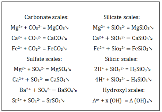
Besides the poor quality of the reinjected water, many studies [21– 24] have proved that the difference in ions composition of the injected and formation water, leads to the formation of inorganic scales of many types. In both waters, the main cations are K+, Na+, F3+, Fe2+, Mg2+, and Ca2+ and the main anions include HCO3-, CO32-, SO42-, and Cl-. The compositions in the formation water are NaCl and Na2CO3. Ca2+ is the main divalent, and Mg2+ is much lower. Therefore, the Ca2+ and CO32- are the dominating ions and the following inorganic scales can result:[25]
Acidizing operations
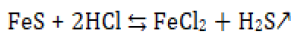
As the injection pressure is getting high and high, the oilfield engineers decided to lead conventional acidizing (HCl) operations to remove the plugging within the platform B formation [26]. The plugging was successfully removed and formation permeability restored [27]. However due to the high content of dolomite and calcite of the formation, the acidizing operations caused damages to the rock structure in the wellbore area, thus making the water injection process more difficult and causing serious secondary damages as well as environmental problems such as hydro sulfuric acid formation according to:[28]
From the above causes, we can say that the reservoir damages on platform B of Bohai oilfield are mainly caused by the internal factors of the reservoir itself and external factors as well. Then the HCl acidizing had made the unplugging process more hazard than wanted to the wellbore area, therefore, it is necessary to carry out new research for unplugging process so to decrease the injection pressure, using non acids components or weak acids ones.
Experimental Part
Determination of the sample composition
Soxhlet extraction: The sample of the plug was obtained from the wellbore area of a water injection well on platform B of Bohai oilfield. In laboratory, we used standard SY 1022 1967, related to solvent extraction of petroleum residues in Chinese oilfields. Following the standard, we ran a double Soxhlet extraction to determine the sample organic and inorganic parts.
SEM&XRD: The sample was proved to be inorganic scale, SEM and XRD analysis were carried out to capture its structure and determine the exact composition in elements.
Removal solution formulation
We aimed to synthetize a new formula effective and not containing any of HCl, HF or others strong acids. For this aim, we screened weak acids, surfactants and solvents to select the most effectives to dissolve/ wash the scale.
Chemicals screening: Different chemicals were screened one by one according to standard SY/T 5673 [30], related to scales removers screening in Chinese oilfields, to calculate their dissolving/washing rates at 0.5% to 5% concentration ranges. As references, analytically pure hydrofluoric acid and distilled water were used respectively as highest and lowest dissolving/washing agents. The dissolving/washing rate by:
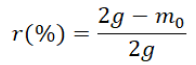
Where, 2g is the mass of the scale used, r is the rate and m0, the dissolved/washed part from the scale given by: m0=m2-m1; where m1 and m2 respectively, the filter’s masses before and after dissolution and filtration.
After screening, five chemicals were selected according to their rates and roles (Table 2) for dissolving/washing the scale.
| Solvent | Volume(mL) | Temperature(°C) | Time(min) |
|---|---|---|---|
| Ethanol | 160 | 90 | 90 |
| Toluene | 140 | 120 | 60 |
Table 1: Extraction conditions.
| Component | Quality | Formula | Used as |
|---|---|---|---|
| Acetic acid | Analytically pure | CH3COOH | Scale dissolver |
| EDTA | Analytically pure | C₁₀H₁₆N₂O₈ | Chelating agent |
| Octyl glucoside | Pure | C₁₄H₂₈O₆ | Scale inhibitor |
| Sodium dodecyl sulfate | Pure | C12H25NaO4S | Active agent |
| Ethanol | Analytically pure | C₂H₆O | Solvent |
Table 2: Selected chemicals for the removal solution.
Final removal solution formula: Plackett–Burman designs are experimental designs presented in 1946 by Robin L. Plackett and J.P.Burman.
Their goal was to find experimental designs for investigating the dependence of some measured quantity on a number of independent variables (factors), each taking L levels, in such a way as to minimize the variance of the estimates of these dependencies using a limited number of experiments [30].
To have the best dissolving rate and minimize the experiments number and time, we got inspired from Plackett-Burman screening design to make a matrix for five different formulas with 5% concentration base for each component and two-level (3% or 2%) concentration range for the four others.
As each solution base is given for every formula, the rest of components can be X1, X2, X3, or X4, in the matrix (Table 3):
| Factors | Base | X1 | X2 | X3 | X4 |
|---|---|---|---|---|---|
| Concentrations | 5% | Highest, 3% = (+) / Lowest, 2% = (-) | |||
| Tests | |||||
| ABS | + | + | − | + | + |
| SBS | + | − | + | − | + |
| SoBS | + | − | − | + | − |
| CaBS | + | + | − | − | + |
| AaBS | + | − | + | − | − |
Table 3: Screening matrix for five runs and five two-level factors.
Removal solution characterization and performances
Solution pH versus temperatures: For chemical solutions, pH variation is one of the most important parameters to determine. We set the temperatures range from 25°C to 70°C.
Temperatures effect on the dissolving process: The solution first dissolving rate was obtained at reservoir temperature (60°C), here we changed the temperatures and calculated the new dissolving rates.
Corrosion rate and speed: The removal solution is surfactants based but has an acid pH at reservoir temperatures due to its weak acids content (Acetic acid and EDTA). Therefore, it might be corrosive to the injection system. We used standard SY/T 5405-1996 [31], related to petroleum products corrosion test in Chinese oilfields to estimate its corrosion rates and speed at different temperatures using N80 steel. Temperatures were set using a static water bath.
The corrosion rate (C) and corrosion speed (vi) are given by:
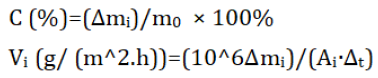
Where, mo is the initial steel mass, Δmi masses difference, Ai the steel surface area and Δt the time difference. Figure 1 below, shows the used steel to test the corrosivity.

Figure 1: N80 used corrosion steels.
Corrosion inhibitors screening: To reduce the proven corrosivity of the removal solution, we used standard SY/T 5756-1995, related to corrosion inhibitors testing for chinses oilfields, to screen two corrosion inhibitors used in the oilfield and an ammonium salt (C3N2H4).
Solution compatibility to formation and injected waters: Turbidity is the measure of relative clarity of a liquid. It is an optical characteristic of water and is a measurement of the amount of light that is scattered by material in the water when a light is shined through the water sample. The higher the intensity of scattered light, the higher the turbidity [32].
To calculate the turbidity, formation and injected waters based on the ions compositions (Table 4) sheets received from the oilfield [33], were synthetized. A digital turbidity meter SGZ-2 to was used and temperatures were set in a static water bath.
| Ions | Formation water | Injected water | |
|---|---|---|---|
| Cations (mg/L) | Na+ K+ | 3183.2 | 2620.74 |
| Mg+ | 26.75 | 78.91 | |
| Ca+ | 128.26 | 230.28 | |
| Anions (mg/L) | Cl- | 4847.79 | 4428.59 |
| SO42- | 67.09 | 287.95 | |
| HCO3- | 241.03 | 50.12 | |
| CO32- | 147 | 11.51 | |
| Total salinity (mg/L) | 8641.12 | 7708.1 | |
Table 4: Waters compositions.
Solution injectivity test by sand pack flooding: The main objective of the solution is to decrease the injection pressure on the oilfield during water flooding by removing the plugging within the formation; we decided to simulate the reservoir and plugging conditions in the lab by running a sand pack flooding experiment [34]. The experiment was ran using the oilfield sand at 60°C, which is the reservoir temperature.Figure 2 below,represents the scheme of the core.

Figure 2: The experiment schematic: a) Tank for injected fluids;
b) Injection pump; c) Pistons; d) Sand pack; e) Injection pressure
gauge; f) Core pressure gauge 1; g) Second core pressure gauge 2;
h)Effluent.
The experiment was ran in four steps:
• Determine the initial sand permeability: The formation water was injected at 1 mL/min until the pressure got stable for at least 1 PV injection volume.
• Create an artificial plugging to increase the pressure, which will represent the plugging pressure: Mix the injected and formation waters at 50/50 ratio and inject the mixture at 1 mL/min to create an inorganic sale within the pack so to reach the highest pressure of the system.
• Test the injectivity of the solution at the plugging pressure: Inject the solution at 2mL/min for 3 PV and record the pressures. • Restore the sand permeability: Inject the formation water at 1 mL/min until stability of the pressure system.
Results And Discussion
Plugging sample composition
Soxhlet extraction: After filtration, the plug was found to be 38.74 Wt.% organic and 61.26 Wt.% inorganic: Images of the plugging of Images of the plugging material are shown in figure 3 below.

Figure 3: Left to right: The plugging sample and its inorganic part.
SEM&XRD: Results of SEM & XRD analysis are below in figures 4 and 5.
From SEM images, the structure of the scale is a dispersed group of spherical balls around a middle one bigger and more compact. Which makes it easy to be disengaged and hence dissolvable in weak acids.
After ZAF correction, the diagram tells that, the scale is oxygen 45.12 At%, carbone 22.54 At%, aluminum 15.99 At%, Silica 15.52 At% and iron 00.83 At%. That makes it an aluminum silicate scale of formula SiOX AlOy
Removal solution formulation
Chemicals screening: Figure 6 below gives the dissolving rates of chemicals used.

Figure 4: Images of the scale at 100, 40.0 and 10.0 μm resolutions.

Figure 5: XRD diagram of the scale elements.

Figure 6: Chemicals dissolving/washing rates.
At low concentrations, acetic acid has shown the highest dissolve rate to the plug compared to the reference of HF acid. Then the glucoside surfactant and EDTA are the second and third respectively.
Final removal solution formula: The Dissolving/Washing rates of the five formulas are given in figure 7 below.

Figure 7: Final formulas dissolving rates.
From the diagram, the best combination to dissolve the scale was the Surfactant-Based Solution (SBS) with 63% of scale dissolved; it contains 5% Octyl glucoside, 2% acetic acid, 3% ethanol, 2% EDTA, and 3% sodium dodecyl sulfate.
Removal solution characterization and performances
Solution pH versus temperatures: The pH values with temperature change are given in figure 8 below.

Figure 8: Solution pH at different temperatures.
At room temperature, the solution had 6.34 pH, almost basic solution. Then with temperature increasing the pH decreased to 5.86 from 60°C to 70°C. That makes it indeed an acid solution at reservoir temperatures but still in the range of the oilfield requirements [5].
Temperatures effect on the dissolving process: Dissolution rates with temperature changes are in Figure 9 below.

Figure 9: Solution dissolving rate versus temperature.
As expected, change in temperatures affects the dissolving process as it increases gradually to reach 72% of scale dissolved at 120°C, while it was only 45% of scale, which was dissolved at room temperature (25°C).
At reservoir temperature (60°C), the solution dissolves 62% of the plug. Compared 77% dissolving rate of the recent removal formulas used in the oilfield (15% HCl and 12% HF+3% HCl) [2], the solution has an acceptable dissolving rate.
Corrosion rate and speed: Corrosion rates and speeds versus are given in Figure 10 below.

Figure 10: Corrosion rates and speeds at different temperatures.
The solution has both corrosion speed and rate at all temperature low compared to what we can find in literature [19]. However is still corrosive enough according to the offshore oilfields requirements which are a plugging removal solution of 5
Corrosion inhibitors screening: Corrosion inhibitors efficiency are represented in figure 11 below.

Figure 11: Corrosion inhibitors rates.
The best corrosion inhibitor was the ammonium salt, as it reduces the corrosivity of the solution from 3.87% to 2.12%, which makes the solution suitable for the oilfield requirements [5].
Solution compatibility to formation and injected waters: Compatibility of production and injection waters are below in figure 12.

Figure 12: Solution turbidity.
The solution has a raw turbidity of 56 NTU, it gets stable with the injected and formation waters around 9.8NTU. That makes it compatible for the B platform, as the limit turbidity needed is 10 NTU [20].
Solution injectivity test by sand pack flooding: The pressure variations during core flooding are given in figure 13 below.
Figure 12: Solution turbidity.

Figure 13: Solution injection pressures.
From the three pressure points we used (injection, core1 and 2 pressures), we focused on the first one, as it is the most representative for the system from its location (input of the pack).
As for the results, it can be seen from Figure 10:
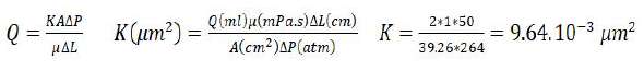
• For the first phase (0 to 8PV), the pressure increases with time until its stability around 0.264 MPa after 6 PV of injection. That gives the initial permeability pressure by:
• The second phase (8 PV to 16 PV), the injection of the mixture of the 2 kind of water created an inorganic scale and increased the injection pressure from 0.264 MPa to 1.043 MPa after 8 PV of injection. That represents the highest pressure we can get as it was about to get stable around that value.
• For the third phase (16 PV to 19 PV), As soon as the solution was injected, the pressure started decreasing to reach 0.617 MPa after 3 PV of injected volume.
• The last phase (19 PV to 27 PV) as mentioned was about the restoration of the permeability, after 6 PV of formation water injection, the pressure was stable around 0.205 MPa until 8 PV. So the new permeability was calculated by:
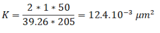
The new permeability is bigger than the first sand permeability.
Conclusion
From previous works, it has been proven that plugging of water injection wells on platform B of Bohai oilfield is due mostly to injected water suspended solids content, reservoir sensitivity to profile control agents, incompatibility between injected and formation waters and acidizing operations. From this present work, we retained:
• The studied plugging sample is an inorganic scale of Aluminum silicate family.
• The new removal solution has good compatibility with formation and injected waters (9.8 NTU), good acid pH (5.8), low corrosion rate (2.12%) and dissolves until 72% of the scale plug.
• The solution has perfect injectivity to the formation sand and decreases the injection pressures of the system of 0.426 MPa within 3 PV of injected volume. It helps as well to restore permeability bigger to the initial permeability of the sand.
• From its characteristics and performances; the solution is good enough for immediate use on site for unplugging the formation during water flooding.
Acknowledgment
This work is a part of the project “Blockage removal technology during water and polymer flooding in Bohai oilfield injection wells, study on samples from platforms A and B”, submitted by China National Offshore Oil Corporation (CNOOC), LTD., Tianjin Branch, Tianjin 300459, and China Oilfield Services LTD (COSL)., Tianjin 300459., and Shandong key research and development program (2019JZZY010349).
A project submitted to our laboratory, the key laboratory of unconventional oil and gas development (China University of Petroleum (East China)), Qingdao 266580, PR China.
Conflict of Interest
The authors declare that they have no conflict of interest.
References
- Lu Q, Ning Y, Wang J, Yang X (2015) Full field offshore surfactant- polymer flooding in bohai bay China. Soc Pet Eng - SPE Asia Pacific Enhanc. Oil Recover. Conf. EORC pp: 312-323.
- T Yi, Jin Z, Chuan-Li X, Wei-Ying W (2014) A Bohai sea SZ36-1 oil field formation scaling experimental study and scale inhibitor optimization. Pet Sci Technol 32: 2512-2519.
- Bin Merdhah AB, Mohd Yassin AA (2007) Scale formation in oil reservoir during water injection at high-salinity formation water. J Appl Sci 7: 3198-3207.
- Li B, Kang X, Zhang J, Tang E, Wei Z, et al (2018) A systematic studyof the effect of plugging on polymer flooding in w offshore oilfield of bohai bay.Proc. - SPE Symp. Improv. Oil Recover.
- Yuan JB, Wood DA (2018) Overview of Formation Damage During Improved and Enhanced Oil Recovery. Elsevier Inc.
- Dragomir A, Precupanu V, Arsenoiu V, Tippel P, Radulescu G, et al (2013) Case study analysis of formation damage induced by brine workover fluid on burcioaia reservoir (romania) and research on damage removal methods. SPE - Eur. Form. Damage Conf. Proceedings, EFDC 1:126-146.
- Nasr-El-Din HA,Al-MohammadAM,Al-HajriMA,ChessonJB ( 2005) A new chemical treatment to remove multiple damage in a water supply well. SPE - Eur. Form. Damage Conf. Proceedings, EFDC: 509- 517.
- Mitchell RW, Grist DM, Boyle MJ (1980) Chemical Treatments Associated With North Sea Projects. J. Pet. Technol 32:904-912.
- Yuan B, Wood DA (2018) A comprehensive review of formation damage during enhanced oil recovery. J Pet Sci Eng 167: 287-299.
- Bedaiwi E, Al-Anazi B, Paiaman A, Al-Anazi A (2009) Polymer Injection for Water Production Control through Permeability Alteration in Fractured Reservoir. Nafta 60 pp: 221-231.
- Chen T, Wang Q, Chang F, Al-Janabi Y (2016) Iron Sulfide Scale Dissolution at High-Pressure, High Temperature. Saudi Aramco Journal of Technology pp: 47-54.
- Aksland TG, Andrews JS (2006) Observations of well productivity and skin in sand-control completions exposed to precipitation of sulfate scales in the near-wellbore area: A case study. SPE Eighth Int. Symp. Oilf. Scale 2006: 111-129.
- Nasr-El-Din HA (2005) Formation damage induced by chemical treatments: Case histories. J Energy Resour Technol Trans. ASME 127: 214-224.
- Yuan YS, Cao GS, Chen P, Gao Y (2014) A kind of novel chemical plugging removal technology study for polymer flooding wells. Adv. Mater. Res 884-885: 7-11.
- Stalker R, Collins IR, Graham GM (2003) The Impact of Chemical Incompatibilities in Commingled Fluids on the Efficiency of a Produced Water Reinjection System: A North Sea Example. SPE Int. Symp. Oilf. Chem PP: 441-453.
- Yuan B, Wood DA (2018) A comprehensive review of formation damage during enhanced oil recovery. J Pet Sci Eng 167:287-299.
- Moghadasi J, Muller-Steinhagen H, Jamaialahmadi M, Sharif A (2006) Oil Reservoirs and Production Equipment due to Injection of Incompatible Waters. Asia-Pacific J. Chem. Eng 14: 545-566.
- Jaimes MG, Castillo RD, Villar A, Escobar MA, Dorado R, Acevedo NP (2014) Integrated analysis to identify and prevent formation damage caused by completion brines: A colombian field application. SPE Lat. Am. Caribb. Pet. Eng. Conf. Proc 3: 2006-2020.
- Jin SHI, Licheng HE, Xiaoyu W (2013) Study and Application of a New Complex Plug Removal System.5:31-35.
- Awolayo A, Sarma H, AlSumaiti AM (2014) A laboratory study of ionic effect of smart water for enhancing oil recovery in carbonate reservoirs. SPE EOR Conference at Oil and Gas West Asia.
- BinMerdhah AB, Yassin AAM, Muherei MA (2010) Laboratory and prediction of barium sulfate scaling at high-barium formation water.J Pet Sci Eng 70:79-88.
- Nasr-El-Din HA (2005) Formation Damage Induced by Chemical Treatments: Case Histories. J Energy Resour Technol Trans ASME 127: 214-224.
- Kamal MS, Hussein I, Mahmoud M, Sultan AS, Saad MAS (2018) Oil field scale formation and chemical removal : A review. J Pet Sci Eng 171: 127-139.
- Bader MSH (2006) Sulfate scale problems in oil fields water injection operations. Desalination 201: 100-105.
- Wang ZH and Zhuge XL (2014) An environmentally-friendly method for removing polymer plugging in well boreholes. Pet Sci Technol 32: 2763-2769.
- Zhu D, Hou J, Wang J, Wu X, Wang P, et al., (2018) Acid-Alternating- Base (AAB) technology for blockage removal and enhanced oil recovery in sandstone reservoirs. Fuel 215: 619-630.
- Ramzi M, Hosny R, El-Sayed M, Fathy M, Moghny TA (2016) Evaluation of scale inhibitors performance under simulated flowing field conditions using dynamic tube blocking test. Int J Chem Sci 14: 16-28.
- Chen C, Guo J, An N, Pan Y, Li Y, et al., (2012) Study of asphaltene dispersion and removal for high-asphaltene oil wells. Petroleum Science 9: 551-557.
- Carrillo-Cedillo EG, Haro-Vazquez MP, Diaz Trujillo GC, Canizares- Macias MP (2014) Plackett-burman factorial design for the optimization of a spectrophotometric flow injection method for phenol determination in tap and bottled water using 4-aminoantipyrine. J Mex Chem Soc 58: 99-105.
- Wang Q, Shen S, Badairy H, Shafai T, Jeshi Y, et al., (2015) Laboratory assessment of tetrakis (hydroxymethyl) phosphonium sulfate as dissolver for scales formed in sour gas wells. Int J Corros Scale Inhib 4: 235-254.
- Tahir M, Hincapie RE, Foedisch H, Abdullah H, Ganzer L (2018) Impact of sulphates presence during application of smart water flooding combined with polymer flooding. SPE Europec featured at 80th EAGE Conference and Exhibition, Copenhagen, Denmark.
- Kotlar HK, Selle OM, Haavind F (2002) A ‘Standardized’ Method for Ranking of Scale Dissolver Efficiency. A Case Study from the Heidrun Field. International Symposium on Oilfield Scale, Aberdeen, United Kingdom 30: 157-168.
- Gray DH (1966) Formation Damage in Sandstones caused by Clay Dispersion and Migration. Clays Clay Miner 14: 355-366.
Indexed at, Crossref, Google Scholar
Citation: Moussa Z. Salim, Kang Wanli, Hongbin Yang, Chao Chen, Xiaoyu Hou, Yuxi Li , K. Shola and Ming Lu (2021) Synthesis and Characterization of a New Solution to Remove Plugging During Water Flooding: Study Case, Platform B of Bohai Oilfield.. Oil Gas Res 8:. DOI: 10.4172/2472-0518.1000219
Copyright: © 2022 Salim M.Z. This is an open-access article distributed under the terms of the Creative Commons Attribution License, which permits unrestricted use, distribution, and reproduction in any medium, provided the original author and source are credited.
Select your language of interest to view the total content in your interested language
Share This Article
Recommended Journals
Open Access Journals
Article Tools
Article Usage
- Total views: 5307
- [From(publication date): 0-2022 - Nov 13, 2025]
- Breakdown by view type
- HTML page views: 4462
- PDF downloads: 845