Research Article Open Access
Dual Band UWB Antenna Design and Simulation
P.S.Ashtankar1* and Dr.C.G.Dethe21Department of Electronics & Communication Engineering, Kits, Ramtek(M.S.),India
2Priyadarshini Institute Of Engineering & Technology, Nagpur (M.S.), India
- *Corresponding Author:
- P.S.Ashtankar
Department of Electronics & Communication Engineering, Kits, Ramtek(M.S.),India
E-mail: cgdethe@gmail.com
Visit for more related articles at International Journal of Advance Innovations, Thoughts & Ideas
Abstract
This paper proposes a miniaturized size of UWB antenna design to fit the existing USB dongles with a typical width of 22-28 mm. The design is based on a small printed UWB antenna [5] with dimension of 25 mm× 25 mm × 1.6 mm. The ground-plane effect on impedance performance of the antenna has been significantly reduced due to the length of the radiator. The shape of the proposed design above half circular disk extends the effective current path and concentrates majority of the current on the radiator instead of the system ground plane. This idea is an effective method to assuage the problem of the ground plane reliance. This small printed antenna should be reduced further in order to fit within the W-USB dongle for future wpan applications. This newly simulated structure is fabricated on FR4 with εr=4.4, tanδ=0.02 and thickness of 1.6mm. It is shown that return loss of the antenna at 7 GHz is better than -10 dB.
Keywords
UWB, WPAN, W-USB.
Introduction
Compact size, low-cost printed antennas with Wideband and Ultra wideband characteristic are desired in modern communications systems. Dipole antennas have been popular candidates in many systems for their various advantages, such as Light weight, low cost, ease of fabrication, etc. Normal dipole antennas are with relatively narrow bandwidth; about 10% for VSWR of 2 This bandwidth problem has limited their application in modern wideband and multi-band communication systems. In addition, nearby objects easily detune the dipoles because of the limited bandwidth of operation. Recently, many monopole and circular shape based
Planar antennas have been developed for UWB communication systems. Various planar shapes, such as square, circular, triangular, and elliptical shapes, of monopole antenna are analyzed and reported. Compared with monopole based planar antennas, the design of ultra wide band circular ring type antennas is difficult because of effect of the ground Plane. For expanding the bandwidth of circular ring antenna, the arms are usually designed with fat wire or metal wide circular planar structure. Many designers have tried various ways to improve the structure of the traditional circular antennas, and many valuable results have been obtained. A trisul shape antenna is proposed in this paper. Its bandwidth is greater than 30% for VSWR < 2.Ultra-wideband (UWB) radio technologies draw big attentions considering the applications to the short range wireless communication, ultra-low power communication, ultra-high resolution radar etc., among them, the standardization of the UWB radio is ongoing under IEEE 802.15 WPAN High Rate Alternative PHY Task Group 3a (IEEE802.15.3a) [1,2] and wireless personal area network (WPAN) is originated by the Bluetooth (IEEE802.15.1). IEEE802.15.3a is trying to establish the new standard of WPAN to drastically increase the data rate, which is a weak point of Bluetooth. Now IEEE802.15.3a considers the use of UWB, following the tentative regulation of FCC (Federal Communications Commission, USA), to achieve the bit rate of 110 Mb/s at 10 m and 200 Mb/s at 4 m [1,3] Although the standardization has been at the final voting stage for more than half a year, the first candidate Multi-Band OFDM [4] has not been able to gain the required 75 % approval, and has been in competition with the second candidate DS-UWB [5].
Important parameters in the design of UWB antennas
The following properties are required for the UWB antennas: Linear phase and constant group delay in directivity: If the group delay is not constant, the pulse waveform is spread out in the time domain. Low return loss over ultra wide bandwidth: If there are mismatches both at the antenna end and the circuitry end, the overall dispersion characteristic is much degraded due to the multipath within the feeding cable. Constant directivity over ultra wide bandwidth: The variation of the directivity according to the frequency results in the ripples of the frequency transfer function in some citation direction. The dispersion characteristic is then degraded. There are two fundamental principles to achieve the broadband or UWB property of the antennas [9]
Self-similarity antenna: A self-similarity antenna is with the constant electric shape over the wide frequency bandwidth. Here, the electric shape means the shape described in the dimension of the wavelength. A biconical antenna, a bow-tie antenna, a discone antenna, an equi-angular spiral antenna are the examples of this class.
Self-complementary antenna: A self-complementary antenna is usually composed of planar conductor(s), and its complementary structure is identical to the original structure. Here, complementary structure is obtained by replacing the conductor and the non-conductor parts in the plane. Among the self-complementary antennas, the log-periodic antenna is well known.
Antenna Configuration and Design
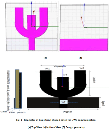
The geometry, parameters, top and front views for a planar Trisul -shaped antenna are shown in Figure 1. The antenna consists of trisul -shaped patch, 50micro strip line and ground. The planar structure parallel to x-y plane; micro strip line is along the y-axis.
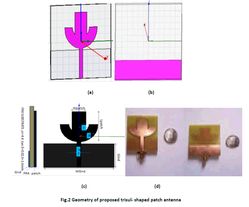
Top view and front view of modified trisul -shaped patch antenna are indicated in figure 2. The proposed antenna is designed on a FR4 substrate with dielectric constant εr = 4.4 and height of the substrate is h =1.6 mm. The substrate has length L= 25mm and width W=25mm.The substrate is mounted on ground of 6.2 mm length and 25 mm width. The inner and outer dimensions are same
Design, Investigation and Optimization of a Compact UWB Antenna
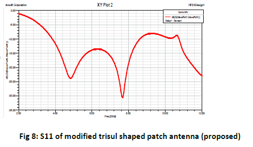
As mentioned above, UWB technology has gained great popularity in research and industrial areas due to its high data rate wireless communication capability for various applications. As a crucial part of the UWB system, UWB antennas have been investigated a lot by researchers and quite a few proposals for UWB antenna design have been reported [12-20].However, the design of those proposed papers are quite complex and tolerance of those special features/variables on the antenna design will be a big issue when it goes to mass production. Hence, this has motivated us to design up a very low complexity, low cost and compact antenna to cover a very wide frequency band including Satellite Digital Multimedia Broadcasting (S-DMB), Wireless Broadband (WiBro),Wireless Local Area Network (WLAN), China Multimedia Mobile Broadcasting (CMMB) and the entire UWB. In this case study, we present a very simple rectangular (no perturbation) planar antenna having the operating bandwidth ranging from 2GHz-12GHz by integrating various technologies into one compact antenna. We start with a simple circular monopole planar antenna fed by a 50Ω micro strip line with a truncated ground plane. Next, based on the study of the feeding position and current distribution, the antenna is designed to have the operating bandwidth covering the entire UWB, i.e. 3.1GHz-10.6GHz. Then, studies upon the size of the partial ground plane are done to increase the bandwidth towards the lower side of the frequency spectrum, rejecting the bands for WLAN (2.4GHz-2.484GHz) and CMMB (2.635GHz–2.66GHz). Thus the proposed antenna can be applied in various applications: S-DBM, Wibro, WPAN, CMMB and the entire UWB. The operating bands are evaluated by HFSS11 with the criterion of return loss S11 less than -10dB. Simulated radiation patterns over the whole frequency bands are acceptable.
Simulation Results
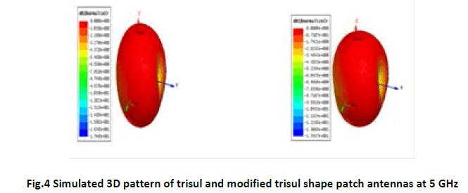
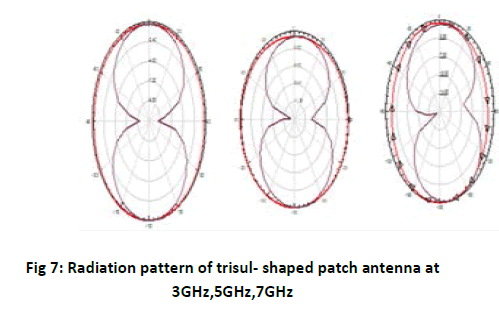
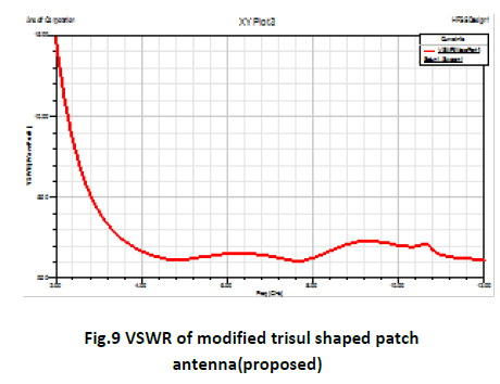
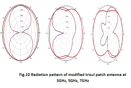
The performance of UWB response depends on a number parameters, such as gap (g) between radiating patch and ground plane, width (wp) and length (Lp) of the patch and total width (wsub) and length (Lsub) of the substrate. The parameters which have significant effect on UWB response are analyze and studied. The gap between the radiating patch and the ground plane `g' affects impedance bandwidth because it acts as a matching network. The optimum UWB impedance bandwidth with dual band notched characteristic is obtained at g = 1.5 mm. The simulated VSWR of proposed antenna is shown in Figure9. The WiMAX band rejection can be tuned by changing the dimensions of Wsub, Lsub, Wpatch, Lpatch. The central band rejection frequency increases with decrease in Wp and rejection bandwidth decreases with decrease inLp. These parameters can be tuned separately to get the notched band. The simulated S11, VSWR and radiation pattern of trisul and proposed antenna are shown in Figures 5, 6, 7, 8 and 9, respectively.
Conclusion
A dual band miniaturized printed UWB antenna has been proposed for WPAN application. The modified trisul shaped patch antenna is simulated using HFSS11. The proposed antenna has the advantages of small size, easy fabrication and simple construction. The simulated results of radiation pattern at 3, 5, 7 GHz and S11 (return Loss) is also presented. The proposed antenna for return loss is less than -10 dB and VSWR is nearly 2 have shown that the antenna can be good candidate for ultra wide band application at the operating frequency of 7 GHz.
References
- First Report and Order, Revision of Part 15 of the commission's rules regarding ultra-wideband transmission systems," Federal Communications Commission, FCC 02-48, 2002.
- C. A. Balanis, Antenna theory analysis and design, John Wiley, c1997.
- H. Schantz, “The Art and Science of U ltra-wideband Antennas”, London, Artech House, 2005.
- Z. N. Chen “Antennas for Portable Devices,” Institute for Infocomm Research Singapore, New York, John Wiley&Sons Inc, 2007.
- L. Yang;and G. B.Giannakis, Ultra-wideband communications: an idea whose time has come,IEEESignal Processing Magazine,pp.26–54, Nov. 2004.
- Lin, Y. C. and K. J. Hung, \Compact ultra wideband rectangular aperture antenna and band-notched designs," IEEE Trans. Antennas Propagation, Vol. 54, No. 11, 3077-3081, 2006.
- Chung, K., S. Hong, and J. Choi, “Ultra wide-band printed monopole antenna with band-notch filters,"IET Microwaves, Antennas and Propagat., Vol. 1, No. 2, 518-522, 2007.
- Chu, Q. X. and Y. Y. ang, \A compact ultra-wideband antenna with 3.4/5.5 GHz dual band-notched characteristics," IEEE Trans. Antennas Propagation, Vol. 56, No. 12, 3637-3644,Dec. 2008.
- Luo, L., Z. Cui, J. P. Xiong, X. M. Zhang, and Y. C. Jiao, \Compact printed ultra-wideband monopole antenna with dual band-notch characteristic,"Electron. Lett., Vol. 44, No. 19, 1106- 1107, Sep. 2008.
- Yin, X.-C., C.-L. Ruan, C.-Y. Ding, and J.-H. Chu, \A compact ultra-wideband microstrip antenna with multiple notches," Progress In Electromagnetics Research, Vol. 84, 321-332, 2008.
- Zaker, R., C. H. Ghobadi, and J. Nourinia, \Bandwidth enhancement of novel compact single and dual band-notched printed monopole antenna with a pair of L-shaped slots,"IEEE Trans. Antennas Propagation, Vol. 57, No. 12, 3978{3983, 2009.
- Bi, D. H., Z. Y. Yu, S. G. Mo, and X. C. Yin, \Two new ultra-wideband antennas with 3.4/5.5 GHz dual band-notched characteristics,"Microwave Opt. Tech. Lett., Vol. 51, 2942{2945, 2009}.
- Li, W.-T., X. W. Shi, and Y. Q. Hei, \Novel planar UWB monopole antenna with triple band-notched characteristics," IEEE Antennas and Wireless Propag. Lett., Vol. 8, 1094-1098, 2009.
- Y. Zeng and Y.-C. Liang, “Covariance based signal detections for cognitive radio,” in Proc. IEEE Int. Symposium on New Frontiers in Dynamic Spectrum Access Networks, Dublin, Ireland, April 2007, pp. 202–207.
- Mohammadian, N., M. N. Azarmanesh, and S. Soltani, \Compact ultra-wideband slot antenna fed by coplanar waveguide and microstrip line with triple-band-notched frequency function,"IET Microwaves, Antennas and Propagat., Vol. 4, No. 11, 1811-1817, Nov. 2010.
- Mishra, S. K., R. K. Gupta, and J. Mukherjee, \Parallel metal plated tuning fork shaped omnidirectional monopole antenna for UWB application,"Microwave Opt. Technol. Lett., Vol. 53, No. 3, 601-604, Mar. 2011.
- Gao, G.-P., Z.-L. Mei, and B.-N. Li,”Novel circular slot UWB antenna with dual band-notched characteristic,"ProgressIn Electromagnetics Research C, Vol. 15, 49-63, 2010.
- Edalati, A. and T. A. Denidni, “A compact UWB antenna with dual band-notched characteristics,"Microwave Opt. Tech. Lett., Vol. 52, 1183-1186, 2010.
- Niu, S. F., G. P. Gao, M. Li, Y. S. Hu, and B. N. Li, “Design of a novel elliptical monopole UWB antenna with dual band-notched function," Microwave Opt. Tech. Lett., Vol. 52, 1306-1310, 2010.
- Lee, J. K. and Y. S. Kim,”\A multiband-rejected UWB monopole antenna using inter digital defected ground structure,"Microwave Opt. Tech. Lett., Vol. 53, No. 2, 312{314, Feb. 2011.
- Azarmanesh, A., S. Soltani, and P. Lot,”Design of an ultra-wideband monopole antenna with WiMAX, C and wireless local area network band notches," IET Microwaves, Antennas and Propagat., Vol. 5, No. 6, 728-733, 2011.
- Li, C.-M. and L.-H. Ye, “Improved dual band-notched UWB slot antenna with controllable notched bandwidths," Progress In Electromagnetics Research, Vol. 115, 477-493, 2011.
- HFSS Version 11.0, Ansoft Software Inc., 2009.
- Wu, Q., R. Jin, J. Geng, and M. Ding, \Printed omni-directional UWB monopole antenna with very compact size,"IEEE Trans. Antennas Propagation, Vol. 56, 896-899, 2008.
- Mishra, S. K., R. K. Gupta, and J. Mukherjee, “Effect of substrate material on radiation characteristics of an UWB antenna,"IEEE Loughborough Antennas & Propagation Conference, LAPC, 157- 160, UK, 2010.
- Institute of Electrical and Electronics Engineers. IEEE Std 802.15.1-2005, Wireless Medium Access Control (MAC) and Physical Layer (PHY) Specifications for Wireless Personal Area Networks (WPANs),14June2005.
- Institute of Electrical and Electronics Engineers. IEEE Std 802.15.4-2006,Wireless Medium Access Control (MAC) and Physical Layer (PHY) Specifi-cations for Low-Rate Wireless Personal Area Networks WPANs),
- M . D . Deshpande, „Input Impedance of Microstrip Antenna" IEEE Trans. , Antennas and propagation‟, Vol. AP 30, No. 4, pp. 645 - 650, July 1982.
- J. Bahl & P. Bhartia, „Microstrip Antennas‟ Artech House, 1980.
- IEEE P802.15 Study Group Medical Body Area Networks (SG-MBAN). SG BAN Montreal Interim Meeting Minutes, 20 May 2007. URL ftp://ieee:wireless@ftp.802wirelessworld.com/15/07/15-07-0748-00-0ban-mban-meeting-minute-montreal-may-2007.doc.
- IEEE P802.15 Study Group Medical Body Area Networks (SG-MBAN). SG BAN San Francisco Plenary Meeting Minutes, 16 August 2007. URL ftp://ieee:wireless@ftp.802wirelessworld.com/15/07/15-07-0820-00-0ban-ban-sessions-minute-sanfrancisco-july-2007.doc.
- http://www.ieee802.org/15/pub/
Relevant Topics
- Advance Techniques in cancer treatments
- Advanced Techniques in Rehabilitation
- Artificial Intelligence
- Blockchain Technology
- Diabetes care
- Digital Transformation
- Innovations & Tends in Pharma
- Innovations in Diagnosis & Treatment
- Innovations in Immunology
- Innovations in Neuroscience
- Innovations in ophthalmology
- Life Science and Brain research
- Machine Learning
- New inventions & Patents
- Quantum Computing
Recommended Journals
Article Tools
Article Usage
- Total views: 16222
- [From(publication date):
September-2012 - Aug 29, 2025] - Breakdown by view type
- HTML page views : 11378
- PDF downloads : 4844

