Influence of Particle Impact on the Blade Failure
Received: 10-Feb-2018 / Accepted Date: 20-Feb-2018 / Published Date: 28-Feb-2018 DOI: 10.4172/2168-9806.1000187
Abstract
Numerical simulation was performed to study the effect of particle impact into the blade. By changing the particle radii and its position, damage area was inspected. Numerical simulation shows that particle radii and its position have an important effect on the chipping removal from the blade.
Keywords: Particle; Numerical simulation; PFC2D
Introduction
Numerical modeling
Particle flow code in two dimensions (PFC2D) was used for investigation of the effect of particle impact into the blade [1].
Particle flow code3: In simulation of bonded particle model by PFC2D, blade is represented as an assembly of circular disks bonded together at their contact points and confined by planar walls. The particles are bonded together at their contacts to simulate a competent material. There are two basic bonding models supported in PFC: a contact–bonded model and a parallel-bonded model. A contact bond approximates the mechanical behavior of high strength materials. The contact bond behaves as a parallel bond of radius zero. Thus, a contact bond does not have a radius or shear and normal stiffness’s, as does a parallel bond, and cannot resist a bending moment; rather, it can only resist a force acting at the contact point. The contacts bonds are assigned with specified tensile and shear strength which allows resistance to tension and shear to exist at the contacts until the force at the contact exceeds the strength of the bond. The mechanics of PFC are described in detail [2], and will not be repeater here. In order to generate a contact-bonded particle model for PFC2D, using the routines provided in the following micro parameters should be define d: Ball-to-ball Contact Modulus, stiffness ratio KN over KS, ball friction coefficient, contact Norm al Bond Strength, contact Shear Bond Strength, Ratio of Standard Deviation to mean of bond strength both in normal and shear direct ion, and minimum Ball radius. Defining a parallel-bonded particle model requires three addition al micro parameters, which are: parallel-bond radius multiplier, parallel bond modulus, and parallelbond stiffness ratio. In this study, bonded particle models are created by assuming that particles are joined and bonded together using the parallel-bonded model.
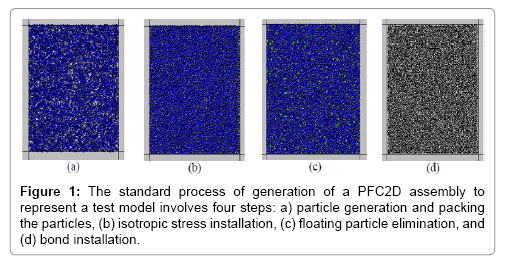
Preparing and calibrating the numerical model: The standard process of generation of a PFC2D assembly to represent a test model involves four steps: (a) particle generation and packing the particles, (b) isotropic stress installation, (c) floating particle elimination, and (d) bond installation.
(a) Particle generation and packing the particles (Figure 1a): a rectangular vessel consisting of planar frictionless walls is created, and an assembly of particles is generated to fill the vessel. The wall normal stiffness is larger than the average particle normal stiffness to ensure that particle–wall overlap remains small. The particle diameters satisfy a uniform particle-size distribution bounded by Dmin and Dmax: to ensure reasonably tight initial packing, the number of particles is determined such that the overall porosity in the vessel is 8%.The particles, at half their final size, are placed randomly such that no two particles overlap. The particle radii are then increased to their final values.
(b) Install specified isotropic stress (Figure 1b): the radii of all particles are reduced uniformly to achieve a specified isotropic stress, σ0, defined as the average of the direct stresses. These stresses are measured by dividing the average of the total force acting on opposing walls by the area of the corresponding specimen cross-section. When constructing a blade material, σ0 is set equal to approximately 1 MPa. This is done to reduce the magnitude of the locked-in forces that will develop after the parallel bonds are added.
c) Reduce the number of floating particles (Figure 1c): an assembly of non-uniform sized circular cans contain a large number of floating particles that have 3 contacts. It is desirable to reduce the number of floating particles such that a denser bond network is obtained. By setting the number of ball contacts equal to 3 and the allowed number of floating particles to zero, we obtain a bonded assembly for which nearly all balls away from the specimen boundaries have at least three contacts.
(d) Install parallel bonds (Figure 1d): parallel bonds are installed throughout the assembly between all particles that are in near proximity. The grain property is also assigned. After the parallel bond installation, the direct tensile test was performed to calibrate the micro properties of particles and parallel bonds in the bonded particle model.
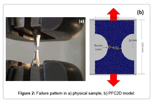
Direct tensile test: Direct tensile test was used to calibrate the tensile strength of specimen in PFC2D model. Adopting the micro-properties listed in Table 1 and the standard calibration procedures [1,2] a calibrated PFC particle assembly was created. The geometry considered in the numerical tests was shown in Figure 2b. The specimen was made of 5,615 particles. The disk was crushed by the upper and lower walls moved opposite from each other with a low speed of 0.016 m/s. Figure 2a and 2b illustrate the failure patterns of the numerical and experimental tested samples, respectively. Tensile cracks were shown by yellow line. The failure planes experienced in numerical and laboratory tests are well matching. The numerical tensile strength and a comparison of its experimental measurements are denoted in Table 2. This table given a good accordance between numerical and experimental results.
| Property | Value |
|---|---|
| Type of particle | Disc |
| Density (kg/m3) | 3000 |
| Minimum radius (mm) | 0.27 |
| Size ratio | 1.56 |
| Porosity ratio | 0.05 |
| Local dumping co-efficient | 0.7 |
| Contact young modules (GPa) | 12 |
| Stiffness ratio (kn/ks) | 1.7 |
| Parallel bond radius multiplier | 1.4 |
| Young modulus of parallel bond (GPa) | 1.7 |
| Parallel bond stiffness ratio (pb_kn/pb_ks) | 3 |
| Particle friction co-efficient | 0.5 |
| Parallel normal strength mean (MPa) | 50 |
| Parallel normal strength std. dev. (MPa) | 5 |
| Parallel shear strength mean (MPa) | 50 |
| Parallel shear strength std. dev. (MPa) | 5 |
Table 1: Micro properties used to represent the steel blade.
| Physical tensile strength(MPa) | 250 |
| Numerical tensile strength (MPa) | 259 |
Table 2: Direct tensile strength of physical and numerical samples.
Numerical simulation of blade and particle
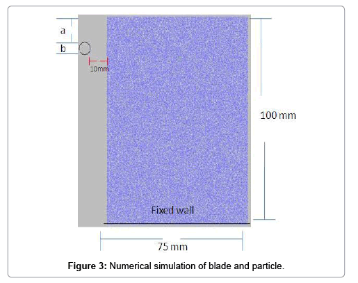
Preparing the model: After calibration of PFC2D, numerical simulation of blade and particle was simulated by creating a box model in the PFC2D (Figure 3). The PFC specimen had the dimensions of 75 ⊆ 100 mm. A total of 11,179 disks with a minimum radius of 0.27 cm were used to make up initial model condition. After model generations, a particle was created in the right edge of the model (Figure 3). Round particle were considered to locate vertically at a distance of 5 mm from the blade’s internal wall (Figure 3). The particles diameters (b in Figure 3) for modeling were set at 1, 2, 4, and 6 mm, vertically located in front of the wall (a in Figure 3) at 0, 5, 10, and 30 mm from the blade tip. The particles hit the blades with the speed of 2 m/s and diffused into 0.2 mm in dept. In all simulations, blades were taken to be static and struck by the moving particle. Totally, twenty simulating performances for different modeling arrangements were executed to investigate the effects of particle diameter and its distance from the blade tip on any possible fracture patterns.
Fracture patterns for blades: Here, the effects of particle diameters and their spacing from the blades on their fracture patterns were discussed. The cracks colored by red and black are differentiating them as those initiated by shearing or tensile, respectively.
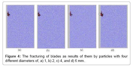
Vertical location of a particle from blade tip in 30 mm distance: Figure 4a-4d shows the fracturing of blades as the results of them by particles with four different sizes.
Figure 4 shows that the blade fracturing is caused by sliding between the disks and their splitting from each other. In all cases, cracks are initiated at particle-blade hitting interfaces and progressed in triangle forms through the remaining indentations. It can be said that by increasing the particle diameter, the sizes of indented areas remain approximately constant. As indentation depth was the same for all, only impact stress caused fracturing in all modeling. Then as the impact stresses are constant for all, the indentation areas remain unchanged too. If the indentation depth becomes larger, then it can be said that the intended areas are affected by disk dimension.
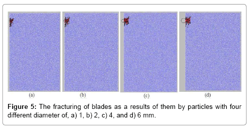
Vertical location of a particle from blade tip in 10 mm distance: Figure 5a-5d shows the blades fracturing as the results of particles (1, 2, 4, and 6 mm in diameters) impacting to.
In all models, shear and tensile cracking initiate under the particles and propagate at indentation surfaces.
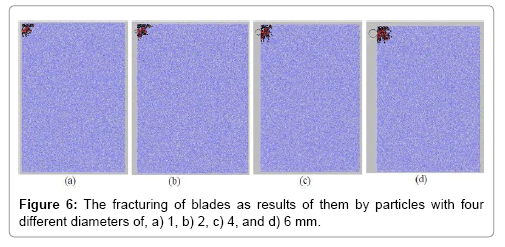
Vertical location of a particle from blade tip in 5 mm distance: Figure 6a-6d shows the blades fracturing as the results of particles (1, 2, 4, and 6 mm in diameters) impacting to.
Tensile and shear cracking patterns on blades are showing crystals sliding and ruptures. These cracks initiate under the particles on blades surfaces and progress towards the tips and also the bulk. The results will be pieces of blades separated from their tips. The fracture patterns in all models are circular with constant fracture surface.
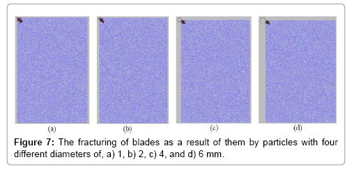
Vertical location of a particle from blade tip in 0 mm distance: Figure 7a-7d shows the blades fracturing as the results of particles (1, 2, 4, and 6 mm in diameters) impacting to.
In general, tensile and shear cracks initiate at the point of hitting blades by particles and they propagate under an angle of 45° through. The length and width of defected areas in all models are similar at 5 mm and 2 mm respectively. In this condition, only the blade tip will be flawed.
It can be said that when the distance between the particle and blade tip is constant then by increasing the particle diameter, the fracture pattern, the fracture surface, and the fracture mode stay unchanged.
Conclusions
Numerical simulation shows that Different hitting points from the blade tip present various morphologies for the fracture pattern. When the distance is at 30 mm, the fracture is triangular and the cracks run through the blade. At distance of 10, the fracture is also triangular with the cracks go towards the tip. At the distance of 5 mm, the fracture is circular and there will be a particle separated from the blade tip. In the case of zero distance, a shear band with the length of 5 mm and the width of 2 mm under an angle of 45° propagate through the blade.
References
- Potyondy DO, Cundall PA (2004) A bonded-particle model for rock. International Journal of Rock Mechanics and Mining Sciences 41: 1329-1364.
- PFC2D I (1999) Particle flow code in 2 dimensions. Theory and background. Itasca Consulting Group Minneapolis MN, pp: 1-124.
Citation: Haeri H, Sarfarazi V, FatehiMarji M (2018) Influence of Particle Impact on the Blade Failure. J Powder Metall Min 7: 187. DOI: 10.4172/2168-9806.1000187
Copyright: © 2018 Haeri H, et al. This is an open-access article distributed under the terms of the Creative Commons Attribution License, which permits unrestricted use, distribution, and reproduction in any medium, provided the original author and source are credited.
Select your language of interest to view the total content in your interested language
Share This Article
Recommended Journals
Open Access Journals
Article Tools
Article Usage
- Total views: 4352
- [From(publication date): 0-2018 - Jun 12, 2025]
- Breakdown by view type
- HTML page views: 3451
- PDF downloads: 901
