Review Article Open Access
Technological Hazards of CO2 Sequestration Activity State of the Art and Experience Feedback at Krechba (In Salah) Pilot Site
Hakima Hamida1*, Aziz Belkhatir2 and Nouredine Tchouar1
1University of Science and Technology of Oran (USTO), Lamosi Laboratory, Oran, Algeria
2Research Institute of Information, Environment IFREI, Paris, France
- *Corresponding Author:
- Hakima Hamida
Risk Engineering PhD
University of Science and Technology of Oran (USTO)
Lamosi Laboratory, Oran, Algeria
Tel: 00-33-617044908
E-mail: ajp.bel@sfr.fr
Received date: October 16, 2015; Accepted date: October 29, 2015; Published date: November 05, 2015
Citation: Hamida H, Belkhatir A, Tchouar N (2015) Technological Hazards of CO2 Sequestration Activity State of the Art and Experience Feedback at Krechba (In Salah) Pilot Site. Ind Chem Open Access 1:109. doi: 10.4172/2469-9764.1000109
Copyright: © 2015 Hamida H, et al. This is an open-access article distributed under the terms of the Creative Commons Attribution License, which permits unrestricted use, distribution, and reproduction in any medium, provided the original author and source are credited.
Visit for more related articles at Industrial Chemistry
Abstract
In order to reduce the CO2 release into atmosphere and thus contribute to reducing the greenhouse effect, the industrial process of CO2 sequestration is still at an experimental stage. This technique of CO2 geological sequestration are not fully controlled and raise issue of technological, environmental, human and organizational hazards and their effects on human health, environment and economy. From CO2 capture to transportation then injecting it into underground natural reservoirs where it is stored, geochemical, geophysical and generally industrial risks are still not very well recognized and identified. The behaviour of CO2 is not yet fully identified deep geological environment. It is therefore necessary to build, in support of this industrial CO2 storage process, proactive analysis of more transversal and overall risk for better control, technological processes of capture, Transport, Storage of CO2 (CTSC).
Keywords
CO2 sequestration; CTSC chain; Technological hazards; CO2 leakage; Krechba pilot site; Chemical risk
Introduction
Meanwhile innovative solutions for the use of clean and renewable energy, to reduce the concentration of greenhouse gases (GHGs) in the atmosphere, industrial processes for capture and storage industrial dioxide carbon (CO2) in the basement, are tested and implemented in the world, on pilot sites in Europe (Norway, France, etc.), North Africa (Algeria, In Salah), North and South America (USA, Canada, Brazil, etc.), Asia (China, Japan, etc.), Australia. According to the Global CCS Institute Australia, 75 CO2 capture and storage projects worldwide are under implementation and 59 projects are under development. With this technical process it would be possible to reduce overall, globally, up to 19% of GHG emissions by 2050.
The use of natural underground reservoirs old oilfield and exhausted gas is one of advanced technical solutions for the storage of some 500-2000 Gt (billion tons) of CO2 for a fairly attractive blow a few euros per ton CO2. Moreover, storage in geological reservoirs formed by the deep saline aquifers allows, meanwhile, burying between 320 and 10,000 GT (billion tons), 10 times more than other selected geological reservoirs, coal seams untapped and basic and ultrabasic rocks. This big capacity of saline aquifers is due to the mechanical adsorption phenomenon, specific to this type of tank, and to physicchemical interactions, those of thermo-hydro-mechanical-chemical nature (THMC) between CO2, brine and the rock that sequester CO2 by phenomena of dissolution and precipitation. This solution is highly sought after by industrials, due to its high sequestration capacity of CO2, its tight structure and its good distribution found widely and globaly across the planet. But it is without taking into account the risks of industrial accidents, those of physic-chemical and geological kindproven but still unknown, involving CO2 in its supercritical fluid and gaseous states and its behavior in underground environments. So, the interest and the efficiency of CO2 sequestration chain are offset by the risks it generates that are not always taken seriously into account. It is necessary to condition the supply chain of CTSC by proactive risk control to make it more safe, reliable, viable and profitable. The experience feedback of storage activity capitalized at In Salah and other pilot selected sites worldwide reveal the risks of this technology in view of vulnerabilities, human health and environmental issues.
Is CO2 Geological Storage economically viable?
Generally, storage sites to date, both the pioneer large-scale industrial CCS operations, e.g., Sleipner, Snohvit (Norway), Weyburn (Canada), InSalah (Algeria), and the small-scale CO2 injection pilots e.g., K12-B (The Netherlands), Frio (USA), Nagaoka (Japan), Ketzin (Germany), Otway (Australia), Lacq-Rousse (France) demonstrate CCS as a feasible technology.
Sleipner is the world’s first CO2 injection project aimed at emissions mitigation. In 1995, the Norwegian government implemented a tax on CO2 emissions and this was an incentive for Norwegian energy company Statoil to start experimenting with CCS on this off shore gass rig.
The Sleipner CO2 storage operation started in 1996, and remains the world’s most mature large-scale demonstration of storage technology with >7 Mt of CO2 currently in situ. Current time-lapse seismic surveys provide a unique, world-leading reference dataset applicable to the general understanding of large-scale storage in saline aquifers
In 1998, a Canadian oil and gas corporation (then PanCanadian Petroleum, now EnCana Corporation) announced to implement a large scale EOR project in an oilfield near Weyburn, Saskatchewan, using CO2 captured from a coal gasification power plant. This provided a chance to demonstrate and study a large-scale geological storage project and to provide the data to evaluate the safety, technical and economic feasibility of such storage.
In April 2008, Statoil announced carbon storage had started on its Snøhvit field – Statoil is reinjecting Snøhvit’s CO2 emissions into the ground beneath the gas-bearing formation on the field. The process will reduce CO2 emissions by 700,000 t a year when Snøhvit is at full capacity, it is estimated. This is the equivalent of emissions from 280,000 cars. The Snøhvit gas fields development comprises three fields – Snøhvit, Albatross and Askeladd. These lie in the Barents Sea, about 140 km north-west of Hammerfest in northern Norway. The fields were discovered in 1984 in 250 m to 345 m of water and extend across seven production licences. Natural gas is first pumped to a carbon capture plan at Melkøya. Here, 5% to 8% of CO2 is removed from the gas and piped back to a 2,600 m deep sandstone formation at Snøhvit, where it sits under the seabed. The storage reservoir is at a depth of about 2500 m, so the technical challenges for monitoring are quite different from those at for example Sleipner.
Current estimates by the IPCC and MIT predict that CCS will require 10-40% more energy per kWh required to isolate carbon. According to the consulting firm McKinsey and Company, this generates additional costs with a cost price per ton of over 100 euros in a phase of experimentation and potentially to 50 euros when CTSC techonology is confirmed and becomes industrialized. But in reality, the power consumption measured on the pilot projects is between 20- 25% with a cost which is currently between 50 and 90 euros per ton. Industrial plan to divide by two this cost for commercial deployments. According to ADEME, “Capture and storage costs are now averaged 60 € per ton” [1]. Table 1, below, gives the elements of the average costs throughout the chain capture - Transport and Storage Geological. One can notice that the “capture” (separation+compression) of carbon is the most expensive. However, transport turns out to be the least expensive item in the chain (it is of course function of distances).
| Capture € / t | Compression €/t | Transport €/t | Injection and storage € / t |
|---|---|---|---|
| 40 | 10-12 | 2 par 100 km | 6 |
Table 1: Average Costs of operations of the chain.
There are seven large-scale installations currently operating worldwide that individually store greater than 0.68 Mt CO2 p.a. (per annum), with a total of 22 Mt p.a. collectively (Global CCS Institute). 1.7 Mt p.a. are stored by two large-scale industrial projects specifically designed for CCS (Sleipner and Snohvit) and the remaining 20.38 Mt p.a. are stored through five Enhanced Oil Recovery (EOR) schemes that utilize anthropogenic CO2 injection (Weyburn, USA/Canada, Val Verde, USA, Enid Fertiliser Plant, USA, Shute Creek gas processing facility, USA, Century Plant, USA). Two further projects in the USA, each with a planned injection rate of 1 Mt p.a., began to inject CO2 in 2013 (Air products methane reformer is providing CO2 for EOR and the Illinois Basin, Decatur Project is storing CO2 in a saline aquifer formation).
Current estimates of total global capacity suggest that up to 11,000 Gt can be stored (IEA Greenhouse Gas R&D Programme), 90% of which is in deep saline aquifers and 10% in depleted oil and gas fields. Based on current estimates, availability of sufficient pore space would not appear to be an issue. However, these assessments are largely based on broad regional studies and need to be refined. The total useable storage capacity of each site, achievable CO2 injection rate and confirmation of local seal integrity will require more detailed research.
The Lacq pilot project (Total) in France is funded by TOTAL whose total cost amounts to approximately € 60 million.
- €40 M for the boiler-capture of CO2 of which € 3 million for safety and the environment
- €20 M for pipes and wells Rousse, including € 4 million for safety and the environment
Total undertook the storage of CO2 between 2010 and 2013 on the Lacq site in the natural gas deposit. A 3-year monitoring phase should demonstrate whether injected CO2 remains confined safely and permanently in the geological formation where it is injected [2].
The physical and chemical risks of CO2 sequestration
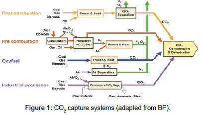
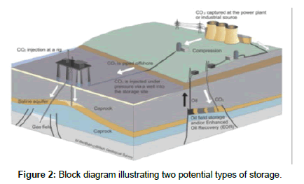
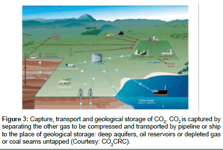
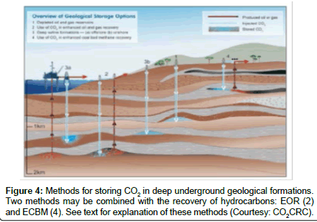
CO2 is first separated and extracted from gases that are used in the composition of various industrial processes (petrochemical and refining, cement, power plant, etc.) It is then captured at the point of issue, compressed and dehydrated in the supercritical state to be transported (pipelines, trucks, boats) to a suitable site where it is injected into geological formations -of saline aquifers, oil and gas deposits depleted, or coal-veins of at least 800 meters deep to a sustainable storage. In the basement, in hydrostatic conditions, CO2 spontaneously become supercritical, from 800-1000 m deep.
The risk of diffuse or massive leaks of CO2 into the atmosphere or into geological basements is major accidental events that may occur during the whole system of CTSC chain (pipeline, well construction, storage volume). Different effects as toxic, thermal (e.g., BLEVE, “boiling liquid vapor explosion expanding”) or explosion can be observed affecting human health (death by asphyxiation) and the environment (pollution saline aquifers environments) [3-6] (Figures 1-4).
In some scenarios of leak or massive eruption of CO2, caused for example by earthquake and depending on the configuration of sites and the environment, given the speed and wind direction, the CO2 could be released into the atmosphere in an unbreathable gas clevis. It would have serious human and environmental consequences with lethal effects by asphyxiation, particularly if the affected sites are settlements, urban areas etc. Such massive CO2 leakage scenario, via unknown failure and vulnerable cracks, or via old wells, degraded and abandoned, can migrate to nearby different environments and reach the potable water aquifers, the surface and the atmosphere, affecting the safety of humans and the ecosystem in general. This scenario is already happened in 1986 at Monoun Lake (Northwest of Cameroon) and NyosLake (Cameroon) where the sudden massive emission of CO2 cloud generated asphyxiation causing the death of 1700 people and thousands of animals.
Depending on the phasesof “capture- transportation - storage of CO2” (CTSC) and their complex technological processesin deep saline aquifer, and based on the feedback and the monitoring carried out on the various pilot sites, we have built a risk map based on the conceptual model of “identification and analysis of systemics risks” –“MADSMOSAR” (malfunction analysis method in systems - organized method systemic risk analysis) P. Perilhon [7-10].
The phases of CTSC and their main risks of leakage and migration
Generally, two contexts, underground and aerial environment, conditioned the issue of risks related to CO2 sequestration. In the aerial context, capture and transport phase are relatively better known than underground environment with injectionand geological storagephase, where geophysical and geochemical backgrounds are not well-known and most delicate and difficult to explore and to understand.
The aerial phase: capture and pipeline transport (coal slurry): In the capture phase, the use of solvents such as amines, ammonia in the post-combustion can create risks, with toxic effects or explosion. The fumes from the post-combustion are loaded with impurities. Oxycombustion is carried out at very high temperatures and requires the production, on site, of oxygen which is a flammable gas generating risks with thermal effects. The pre-combustion requires high pressures and high temperatures; hydrogen (a highly flammable) can be used. Boilers used can have malfunctions and generate therefore the risk of explosion and fire [5].
In the pipeline transportation phase, accidental events are mainly related to piping (leaks and burst pipes due to corrosion, for example etc.). Moreover, the transport process introduces a step of buffer storage, represented by a recompression station for transportation by pipeline to the output of the capture phase, with which the same risk of leakage and explosion may occur. Carbon dioxide as other nonflammable products may cause no BLEVE fireball but with physical explosion and shock wave associated. The risk of cold BLEVE on an overhead transmission line exists [3,5,6].
Underground phases of injection and storage in deep saline aquifer: The risk of accidents in the underground phase mainly concerns the injection well (and its close environment: close-wells) and the geological tank. They occur by diffuse or massive leakage flowing through abandoned wells or still in activity. They can contaminated the surface aquifers (by CO2 or by the toxic brine), or also by CO2 (or native gas) eruptions at handling chemicals or during industrial operation. Generally, the main causes are: the lack of design and construction but also maintenance and monitoring of wells that are no longer watertight, the emergence of the phenomenon of wear and fatigue of materials, operating conditions limits and in degraded mode, the leaks of the control valves of the gas flow, the corrosive nature of the CO2 attacking steel casing, the casing and the cement wells but also the subterranean rock remobilizing and inorganic or organic micro pollutants, degradation of the sealing of the cap rock of the reservoir due to the appearance of cracks or following earthquakes, poor sealing of injection wells, the problem of integrity in terms of abandoned wells, fracturing tank level, the sudden release process of supercritical fluids or eruptive phenomena of mass and leak monitoring the process of formation and dispersal of dense CO2 clouds, multiphase, in the supercritical state in the injection phase, as transport phase or capture phase, which still remain a mystery and cannot be assimilated to gaseous or liquid CO2, the physic-chemical reactions, thermal and bacteriological within the reservoir which disturb the balance of underground environments up etc. [5-11].
In the injection phase, the CO2 is injected continuously in the supercritical state and not submitted to storage-retrieval phases. One considers three technical sub-systems and their specific risks: two surface-storage buffer area and the injection head and underground, the injection wells. During the injection phase of CO2 at least 800 meters underground, these wells are subject to significant temperature differences between fluid and rock as well as the dissolution of materials.
The spatial pattern is composed of three specific areas: the geological reservoir containing CO2 captured, with the area of “near well” storing CO2 in the supercritical fluid state; cap rock, a kind of roof above the reservoir rock and the host on which the tank. The main phenomena contributing to CO2 sequestration are those of mechanical type such as adsorption in the rock tight and chemical nature, that cause different interactions between CO2, brine and the reservoir rock and generating dissolution phenomena (liquid phase) and precipitation (solid phase).
Disturbances of thermo-hydro-mechanical-chemical (THMC) and associated risks: CO2 sequestration is neither neutral nor stable; it induces thermo-hydro-mechanical-chemical and bacteriological disturbances (THMC) which involve the geochemical environment and its dynamic evolution through the various fluids present in the storage tank and the impurities (organic and metal elements) that theycontain. When dissolved gradually in water (brine), CO2 forms carbonic acid, which can dissolve the host rock (especially carbonate) or transform it (new formation of carbonates in silicate rocks). Among the physicochemical phenomena highlighted, there are miscible or immiscible displacement of original fluids, dissolution of the fluids injected in the reservoir fluids, the effects of porosity associated with the permeability of rocks and the possibility to induce seismic activity, and finally the chemical interactions between liquids and solids. These phenomena are aggravated by the impurities that may be present in the injected CO2 such as SOx, NOx, H2S, and Mono-Ethanolamine (MEA) or found in the geological formation. Other types of risk could come from the interaction between the injected CO2 and substances already present in the reservoir rock, such as Metal-Trace Elements (ETM) or organic micro-pollutants.
- Precipitation reactions and associated risks
Furthermore, there is another type of risk related to the existence of precipitation reactions. Indeed, dry CO2 injection will cause drying of the environment in the near-well field. After the acidification stage, the water that was stuck around the injection well evaporates in the injected dry gas, which increases the chemical species in the water. This can result in the precipitation of salts and therefore a decrease in the porosity, like what happens with certain types of cements.
This phenomenon may decrease the injectivity, and therefore significantly reduce the storage capacity
- Pollution risks
Due to this natural phenomenon of dissolution, the brine is contaminated and thus charged minerals (zinc, arsenic, uranium, lead, sulfur oxides, nitrogen, etc.) harmful. Thus, the risk of pollution becomes worse and real as soon as the sealing of the tank is not absolute, initiated by the THMC disturbances described above and induced by the injection of CO2 in the supercritical state (it’s an excellent solvent of organic matter), accelerating dissolution of the reservoir rock, increasing its porosity and cracking. This will cause the migration of polluted brine to Albian underground potable water, for example.
The injection of CO2 in geological tanks containing methane and/ or light alkanes (depleted oil fields, coal seams) may cause desorption of the gases they contain and cause their escape with severe consequence (contamination of the underground potable water, danger of accumulation in confined areas such as cellars, explosive risk, methane leaks, a greenhouse gas, etc.). Consideration of methane leaks must be integrated in the balance sheet of a CO2 storage site to determine the real impact on the limitation of anthropogenic emissions of greenhouse gases.
- Seismic risks and ground movement
CO2 injection induces the elevation of the fluid pressure in the tank, which can lead to an imbalance in the field of the mechanical stresses, mainly close to the injection wells (wells near-field), which may cause fracturing or even the activation of faults that would manifest through earthquakes can degrade the cap rock (the rock cap) or the sealing of wells (especially the old abandoned wells). The damage caused thereby can influence the ability of confining the storage tank and lead to contamination of potable water aquifers or to the mass of CO2 leakage.
Moreover, the injection of supercritical CO2 and the chemical dissolution resulting faults may cause the activation, or compaction of the reservoir rock; which can lead ground motion causing surrection or subsidence of the ground) of the millimeter or centimeter. These movements would likely cause a micro-seismic activity that may be noticeable on the surface. “Contrary to the host rock, a fracture has a high permeability and low emmagasinement, which - if open - allows rapid migration of fluid running through it. At In Salah, faults affecting Carboniferous sandstones, from 1880 m deep, are difficult to detect seismic survey” [12].
Research into reliable outlook for the carbon sequestration process
Technological, physic-chemical and natural hazards related to CO2 sequestration are multiple and complex at once, and the return of experiences capitalized far is still insufficient. It requires further progress in the most precise knowledge of CO2 behavior in the supercritical state but also its evolution and confinement in poorly known underground environments, to better understand the geological, geochemical and mechanical characteristics of storage sites, including, the sealing criteria, porosity, permeability of the reservoir rock, its thickness, and its ability to capture the tectonic and seismic. Many technical and physicochemical locks that directs the Bureau of Geological and Mining Research (BRGM) [13], with its APECO 2 project (Sensitivity uncertainties in Large Scale models for the evaluation of CO2 storage related risks), for example, to develop digital metamodels large scale, based on geostatistics to better infer a reliable approximation of the original model, so the sensitivity approaching uncertainties and more effectively identify CO2 storage riskadaptable to the needs of the users. The European directive on CO2 storage 2009/31 / EC recommends taking into account “the sensitivity of assumptions and choice of parameters on which these models are based to identify the major sources of uncertainty impacting more results simulations “. BRGM Other projects [13] are underway, as ULTimateCO2, which is striving to understand the long-term CO2 storage process, or CIPRES whose goal is to characterize the potential impacts of geological storage of CO2 on quality the groundwater resource.
INERIS [6], for its part, continues to explore and analyze the accident scenarios and risks CTSC chain, especially in terms of technological processes implemented as studies of the soil and subsoil to better understand the behavior of CO2 in the supercritical state, better explore the geochemical environments, geophysics and reservoir rock in the bacteriological and its immediate and distant environment, identify and toxic substances that present a health hazard human, environment and the ecosystem in general, in case of leakage, transfer and migration to other areas, on the surface, in the atmosphere or to other geological horizons [14].
The return of experiments Site Krechba at In-Salah
In Algeria, the pilot site Krechba at In Salah had been chosen as scale test by the authorities to bury 20 million tons of CO2. He is the down dip of the gas production zone, located 200 km from the town In Salah. The region is southern boundary of the Albian table from where the largest water project operations to irrigate vast urban and rural areas between In Salah and Tamanrasset. It is operated by an oil consortium consisting of the Algerian oil company Sonatrach, the British company BP and Norwegian Statoil. The site in question is a former decommissioned gas field, offered to experiment with CO2 sequestration no real “security net” specific, technical, legal and regulatory level, with no real memory of its geological, geophysical, geochemical, environmental and without true knowledge about his condition and its ability to respond to such industrial challenge to apprehend control of this process and its risks, in terms both technical, human, environmental and economic. Thus, of the 20 million tons of CO2 expected to landfills, only 3.8 million tons were kidnapped between 2004 and 2011, according to sources from MIT (Massachusset Institute of Technology), before the sequestration Geological not interrupted in June 2011 due to complications and disorders observed in the Earth’s crust to the surface with a deformation of 5 mm / year, under the effect of pressure of gas stored in the sub soils. The total project cost was estimated at $ 2.7 billion.
Project Description In Salah-JIP
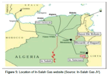
The gas operated In Salah, is loaded into CO2 (5 to 10%). Once “purified”, there, the gas is transported by pipeline to HassiR’Mel a, 450 km distant north, from where it will be marketed. CO2, meanwhile, after being compressed to 180 bar, is sent in an underground water reserve 2 kilometers deep, located on the outskirts of the extraction area of the gas field of In-Salah, to Krechba (Figure 5).
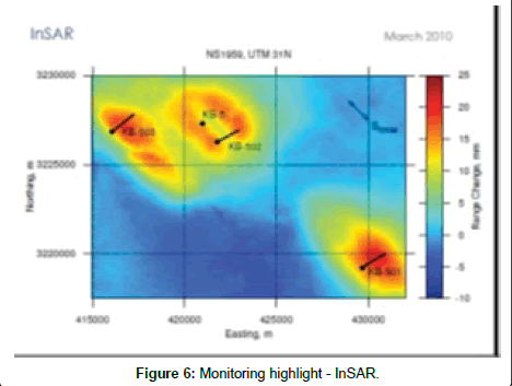
The three horizontal wells Krechba KB-501, KB-502 and KB-503 ensure the CO2 injection. Their horizontal length is 1800 m, the storage formation is 1950 m below ground with 20 m thick, 13% porosity and permeability 10 mD. It is overlaid by impermeable layer 900 m. Wells KB-502 and KB-503 is in an area where the permeability is large, thus the injection is mainly by these two wells. For the well against KB- 501, located in an area with low permeability and low porosity low potential injectivity. Well-9 Kb is itself dedicated to the observation of CO2 leakage while five [15] other wells are used for the observation and monitoring of continental interlayer aquifer (water).
Geochemical and geophysical effects of CO2 storage in the basement of Krechba
Fracture, fault and landslide: Scientific researches concerning krechba pilot site has been handled and undertaken par various américan, norvegian and english researchers as P Ringrose, M Atbi, D Mason, M Espinassous, O Myhrer, M Iding, A Mathieson and I Wright. Key lessons learned framed on the main éelements of the project life cycle: the pre-injection data acquisition, initial design of the monitoring programme 3D, the risk register and risk analysis, modellin and data integration etc. [12]. Smith et al. highlighted the problematic of “Assessment of fracture connectivity and potential for CO2 migration through the reservoir and lower caprock at the In Salah storage site” [16].
Be they natural or artificial fractures greatly influence sequestration. “The raising of the ground surface is highly dependent deformation recovery. Natural fractures, as those artificially induced phenomenon of hydraulic fracturing are the most important factors in the risk analysis of geological CO2 storage sites [17].
The seismic data of 2006, confirmed the existence of fractures and minor flaws in the Carboniferous horizons and layers below the horizon, with reference to images of logging and mud losses while drilling. An injection of a tracer gas with CO2 wells KB-502 was conducted to monitor its progress and its reappearance at the well- 5 and KB model the behavior of fractures. CO2 migration within the Carboniferous is scheduled to follow the northwest and southeast direction (NW-SE) of these fractured [18]. Therefor horizontal wells, injectors and producers, were drilled perpendicular to this direction to maximize the injection and production through these fractures. However, because of the natural depletion of the reservoir, the injected CO2 is expected to migrate injection wells to the gas producing wells.
The results of the monitoring of a satellite-assisted modeling of the reservoir and a “History Matching” of the migration of CO2, the pressure data and satellite strain data were used to build a detailed picture of the distribution of CO2 around the KB-502. They showed the presence of faults in June 2007. A model of the breakthrough curve was used to estimate the permeability of the faulted corridor between 1 and 4 Darcy (permeability hydraulic unit, 1D=0.9869233 × 10⁻¹² m²) with a CO2 leak detected, releasing almost 0.1 tons of CO2. Their openings near the well, estimated from the log data, is in the order of 10-4 to 10-3 m. Injection wells KB-502, the total losses of mud during drilling were correlated to fractures of 1 mm openings while the partial losses correspond to fractures of 0.5 mm openings.
The typo-morphological analysis of the fracture allows identifying several types of flaws, according to their origin or polyphaser history: normal and reverse faults open or closed, old or recent rejection, etc. This variety and complexity in the types of faults associated with the difficulty of their geophysical location make their inclusion and representation in different geological reservoir models, which are used to validate and justify the CO2 storage sites very difficult.
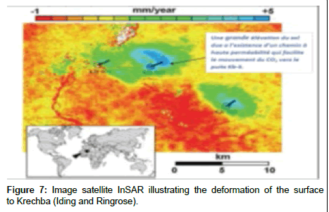
The surface of the ground movements with 10 MPa of pressure increase at the injection site have been detected involving a deformation of the surface of 5 mm/year, reaching an accumulation of 10 to 20 mm, an area of 4 × 5 km eccentric with respect to the injection wells.
These results after lifting from the ground, fractures, plume displacing CO2 and repetitive leaks with CO2 migration to other compartments not provided in advance, the group Sonatrach-BPStatoil took in June 2011, the decision to suspend and stop the CO2 injection work while strengthening the monitoring technique. Newer well data and seismic results are now used to assess the current injection strategy (Figure 6 and Table 2).
| Pre-injection risk register | Risk highlighted during operation | Operational Monitoring Responses |
|---|---|---|
| -Injection well problems -CO2 breakthrough to hydrocarbon production well -Vertical leakage -Wellbore leakage -Legacy well integrity |
-migration to the north -Vertical leakage -Well integrity at KB-5 |
-3D seismic; InSAR, shut-in of well KB 502, integrated modeling. -Reduction og injection, pressure, seismic reprocessing, microseismic data, integrated modeling. Plug-and-abandon KB-5, well-bore studies. |
Table 2: Key risk responses.
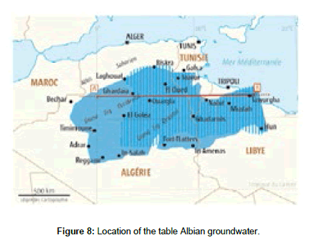
Contamination of surface water bodies and other nearby tanks: In Salah region has a large water table (the table Albian), the largest reserve of fresh groundwater in the world with more than 50000 billion m3 of fresh water that feeds Tunisia, Libya and the Algeria). In 2011, Algeria has launched a mega project of the hydraulic operating table Albian In Salah to Tamanrasset serving all the towns located along the project.
Accordingly achieved CO2 storage, the risk of disruption of water flows into basements is great, the game caused by pressure changes, which can also induce changes in the level of certain aquifers near the surface. Toxic products from the injected CO2 (impurities) or initially referred deep reservoir (heavy metals) could thus be trained and back into the basement through areas of weakness recovery (faults, facies changes) or abandoned wells. Similarly, brines could be displaced and increase the salinity of the superficial aquifers used for drinking water supply, or even of free CO2 which may spawn one or more paths (Leakpaths) through the old wells or through cracks (or fractures) to contact the other more superficial aquifers or reservoirs with neighboring exploited for other purposes (Figures 7 and 8).
BRGM conducted in June 2012, a study (soil analysis, rocks, water, gas, etc.) the risk of leakage of stored CO2 and possibilities of contamination of the immense sheet Albian freshwater Northern Sahara in the immediate vicinity of Krechba site, BRGM Initial investigations have concluded a very marginal risk of leakage. Other further analyses, in situ, provided by BRGM, are expected [19].
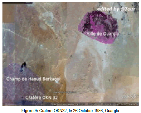
The geological oil tanker disaster site Berkaoui, October 26, 1986 in the province of Ouargla in Algeria, is still remembered. Land subsidence created a crater 200 meters in diameter and 80 meters deep on the oilfield HaoudBerkaoui, southwest of the city of Ouargla. At the root of such a major accident, improper drilling continued on both “accidental maneuver”, cementing and inadequate equipment to the oil wells OKN-32 that was suddenly engulfed. A few months later, in spring 1987, the crater has spread to the nearby oil wells OKN-32a and is extended to 320 m in diameter. The collapse contributed to a higher groundwater salinization creating a risk to the very existence of the city of Ouargla and the disappearance of its gardens and its palm grove. The crater continues to grow inexorably, with major environmental consequences on the Ouargla region (Figure 9).
Conclusions
According to the Intergovernmental Panel on Climate Change (IPCC), the geologic sequestration will be available and ready to be used as a part of greenhouse gas emissions reduction program in 2030 and reliable not before 2050. There is a need to integrate proactive and systemic approaches of risk to support the development and implementation of carbon sequestration chain. This helps to better understand and highlight the accidental phenomena of the supply chain of CTSC and their effects on humans and the ecosystem in general. The necessary acceleration of CCS development and deployment requires an increase in the number of pilot projects and demonstrations as well as the number of research activities on CO2 storage, for a range of site-specific, regional, and generic issues. Research topics requiring focus in the short term include more accurate definition and mapping of storage capacity, improving and integrating different aspects of modeling, pressure management and injection strategies for saline aquifers, improved knowledge on fault behaviour, impact of geological heterogeneities, impact of CO2 impurities resulting from the capture process, improved and innovative monitoring techniques and strategies (higher resolution, real-time, cheaper, able to monitor changes due to physical and chemical processes, at any depth and at any time), mitigation and remediation techniques and strategies and interactions with other uses of the subsurface (e.g., geothermal energy, hydrocarbon reservoirs, water resources).
References
- ADEME (2013) Captage et stockage géologique du CO2 (CSC). Les avis de l’Ademe 1-5.
- Dodds K (2009) In Salah CO2 JIP: Status and overview. Presented at the 5th IEA GHG R&D Programme Monitoring Meeting, Tokyo, Japan
- L’INERIS (2011) modélise les risques du stockage de CO2 en aquifère salin :Beaucoup d’inconnues relatives aux impuretés encore à déterminer. 1-2.
- INERIS (2010) État de l’art sur l’évaluation des impacts, sanitaires et environnementaux du stockage Géologique de CO2. Rapport d’étude INERIS-DRS-10-100825-02286D, EUREKA.
- INERIS (2010) État de l’art et analyse des risques pour un stockage de CO2 en aquifère salin. Rapport n°1: les risques en phase d’injection.
- INERIS (2013) Retours d’expériences des incidents et accidents sur des sites d’exploitation ou de stockage en milieu souterrain- application au stockage géologique du CO2. DRS-12-126009-13866-unique- 1397139450, Rapport d’études.
- Belkhatir A (2010)Systémie, complexité, lois du chaos et MCR-Nouveaux concepts et construits pour une science du danger en devenir.IFREI Paris. 1-27.
- Belkhatir A (2012) Secure gas transportation and distribution in urban area-safety system of gas network and urban planning. World gas conference IFREI Paris 2-6.
- Belkhatir A, Hamida H (2014) Une ingénierie système relativisée dédiée à la sécurisation du processus de piégeage du CO2 industriel, ouvrage collectif, Gestion des risques naturels, technologiques, Ed. Cépadues, France.
- Perilhon P (1999) Réflexion sur les modèles de la science du danger. Ecole d’Eté – Gestion Scientifique du Risque, Albi, France.
- Rutqvist J, Vasco DW, Myer L (2009) Coupled reservoir-geomechanical analysis of CO2 injection at In Salah,Algeria. Energy Procedia1: 1847-1854.
- Ringrose P, Atbi M, Mason D, Espinassous M, Myhrer O, et al. (2009) Plume development around well KB-502 at the In SalahCO2 storage site. First Break 27:85-89.
- BRGM, Bureau de la Recherche Géologique et Minière (2015).
- Wright IW, Mathieson AS, Riddiford F, Bishop (2010) In Salah CO2 Storage JIP: Site Selection Management, Field Development Plan and Monitoring Overview. Energy Procedia 614-1000.
- Davies E, MacDonald B, McColpin G (2009) CO2 Sequestration InSAR Monitoring Phase I: Archival Analysis of Well KB-502 In Salah/Krechba Field, Algeria. Pinnacle-MDA Report for JIP.
- Mason D, Taylor M, Espinassous M, Zinner C, Keddam M, et al. (2010) In Salah Gas Joint Venture: Operating Experience for the CO2 Carbon Capture and Storage Project in the Krechba Field, Algeria. Int. Conference on Greenhouse Gas Technologies GHGT-10, Amsterdam.
- Iding M, Ringrose P (2009) Evaluating the impact of fractures on the long-term performance of the In Salah CO2 storage site. Energy Procedia 1: 2021-2028.
- Mathieson A, Midgley J, Dodds K, Wright I, Ringrose P, et al. (2010). CO2 sequestration monitoring and verification technologies applied at Krechba, Algeria. The Leading Edge.
- Smith J, Durucan S, Korre A, Ji-Quan Shi, CaglarSinayuc (2010) Assessment of fracture connectivity and potential for CO2 migration through the reservoir and lower caprock at the In Salah storage site. Energy Procedia 4: 5299-5305.
Relevant Topics
Recommended Journals
Article Tools
Article Usage
- Total views: 15522
- [From(publication date):
December-2015 - Aug 16, 2025] - Breakdown by view type
- HTML page views : 10836
- PDF downloads : 4686

