To Overcome the First Disadvantage in the Fight against Global Climate Change, which Suggest New Generation Equipment and Needed New Technologies
Received: 23-Jan-2018 / Accepted Date: 31-Jan-2018 / Published Date: 07-Feb-2018 DOI: 10.4172/2573-458X.1000146
Abstract
From identifying the disadvantages of the classic dust separator, we propose the appropriate solutions to overcome these disadvantages and we have obtained nine different types of dust separators for dust collection from different industrial emissions. These new dust separators allow us to recover almost completely the industrial dust contained in various industrial emissions streams. Examine the classic reactor for the classic solid-liquid-gas heterogeneous system, find that it has disadvantage and find a solution to overcome that disadvantage and that we have a new solid-liquid-gas heterogeneous reactors. This devices can be intermittent or continuous, and when assembled we will have combined gas-solid-liquid heterogeneous reactors with industrial capacity to meet the requirements of industrial practice. From these new devices, we can propose three new technologies: No-waste technology for treatment and reuse industrial emissions, CO2 capture from industrial gases in the form of powder NaHCO3, CO2 capture from industrial gases in the form of food clean liquid CO2 or dry ice.
Keywords: Cyclone; Mist spray; Dust extractor; Heterogeneous reactor
Some New Types of Typically Equipment
The new dust separators
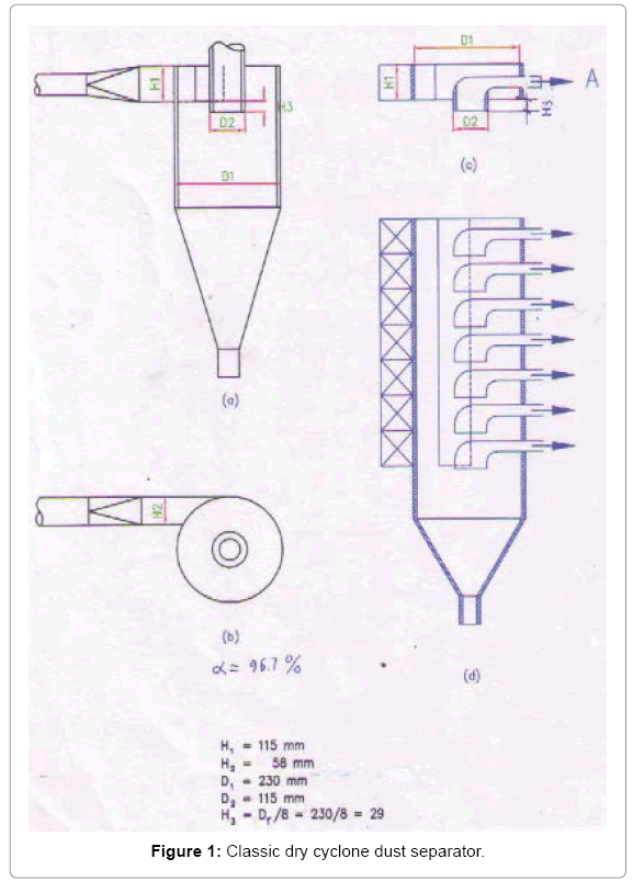
Upgrade dry and wet cyclone dust separators: Figure 1a shows the classic dry cyclone dust separator. Exhaust flow is directed into the cyclone, and the air flow will collide with the inside surface of the cyclone by tangentially direction. These are the classical cyclone dust separator has the following disadvantages:
• Inertial motion: The particles collide with the cyclone was implemented in inertial motion from outside into the cyclone, so the force of impact is very small and only 1 time collision.
• Elastic collides: Collisions between particles with the cyclone is elastic, meaning that after the collision the particles will separate from the cyclone and if the small. Sized particles or light, it will be gone with the gas flow.
• Not have a trap: On the inside surface of the cyclone does not have a trap to capture dust particles after a collision with a cyclone, this also makes the particles after collision are also gone to gas flow swept away. In other words, classical cyclone dust separator will only recovered are large particles, typically greater than 10 μm.
• Not treat toxic chemicals: Not interested in the handling of toxic chemicals in the gas stream such as acidic oxides.
• Not using condensation of water vapor in the exhaust gas: Separation process dust regular occurs at room temperature, not taking advantage of the efficiency of the condensation stream in the exhaust to separate the very fine dust.
• Not able to separate extremely smooth dust particles
• Capacity: Dust extraction capacity is too small.
• Unstable exhaust stream: The classic cyclone requires that the straight velocity of the dust air flow needs to optimal, by the way it cannot be used when unstable exhaust stream.
• Centrifugal force: Unknown generates centrifugal force large enough to separate the dust.
• Filter effect: Do not use the filter effect to separate the dust.
To overcome the disadvantages of the classic cyclone, we have proposed a upgrade dry and wet cyclone dust separator [1,2]. The machine is upgraded as follows. On the inner surface of the cyclone covered with a multi-layered grid to trap the dust, the gas inlet path is extended to 3/4 the diameter of the cyclone with a constant cross section, forming a tunnel that overlays the mesh surface, which means that gas flows with the dust moves along this tunnel with nearly constant velocity. This mesh is constantly vibrating, so the dust is not clogged and falls continuously, and the eventually exits. In the case of wet dust extractor, we also upgrade as above, we install fog nozzles to cool down the air stream, and generate a continuous stream of alkaline solution onto the mesh to neutralize acid oxides in the exhaust stream and to collect dust from the layers of mesh, the layers are not vibrating, the dust is basically recovered in the dry state when passing through the upgraded dry cyclone, leaving a small fraction extremely small along with toxic chemicals are recovered and treated with upgraded wet cyclones. So in industrial practice, we have to use 2 dust separators at the same time: an upgraded dry cyclone and an upgraded wet cyclone. However, dust extraction machines [1,2] have the disadvantage it is small capacity, to meet the requirements of dust extraction from large emission streams, which can reach up to several millions m3/h we have to combine single cyclones together. Figure 1 shows the process of combining dry or wet dust separators, we take the dust separating part of the dust separator 1a, it is Figure 1c, overlapping the 1c we will have individual combined row of upgraded cyclones 1d, combine these single combined sequences 1d, which operate on a parallel principle that will have a combined cyclone dust separator of the scale required by us [3,4].
Dry and wet centrifugal cyclone dust separators
The upgraded cyclone dust separators have the following disadvantages:
1. Requires straight velocity of gas stream into to optimal.
2. In that places, the source gases are unstable is not used.
3. Centrifugal force, by which the particles can be separated from the gas stream, the force due to the same air flow that is generated, not by the mainstream consciousness of man.
To overcome the above drawbacks of upgrade dry and wet cyclone separators we recommend dry and wet centrifugal cyclone [5,6]. All these measures have been used to upgrade the cyclone we will use to this kind of centrifugal cyclone. The dust emission lines are led into the machine, and the gas line suffered tremendous centrifugal force caused by the fan placed in the center of the machine generated, dust particles have to separate from the air stream under that huge thrust of centrifugal force, while airflow must win centrifugal force to escape. Nearly all of the dust particles separated by centrifugal dry cyclone dust separator but partly with very fine dust with toxic chemicals will be separated by wet centrifugal cyclone dust separator.
Dry or wet centrifugal filter cyclone dust collectors
In new machines [1-6], different centrifugal forces have been utilized to separate the dust, and a very effective method of dust extraction is separating dust by suitable filters [1-6]. Do not know how to make use. To overcome this disadvantage of the machines [1-6], we propose dry or wet centrifugal filtered dust separators [7,8]. In this machine we also cover a multi-layer grid on the inner surface of the cylinder. In addition, the membrane is placed centrally to the dust separator. The dust gas flow enters into the machine, and evenly distributed to the outer surface of the filter membrane on the cyclone type. The centrifugal blower is centrally located in the machine, which is retained by the membrane, because the membrane vibrates continuously, so the dust falls downwards, and then leads out, because the centrifugal force of the gas flow is small so easily over the filter and out. There are two types of centrifugal separators: Dry centrifugal filter and wet centrifuge filter.
The New Solid Liquid Gas Heterogeneous Reactors (SLGHR)
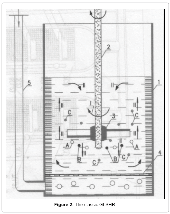
To perform reactions between the constituents A, B, C above, we have to mix with the required velocity. Rotary axis 2 makes stirring paddle 3 move, because it structured propeller, paddle should create 2 dimensional motions (see arrow) of the constituents in the reactor, which are (I) and (II). Direction (I) is the rotation around stirring axis , and direction (II) move from top-down or bottom-up, along the stirring axis. Of course such a stir quickly to make the system uniform. What we need is to comment them moving together, that is if they move with the same speed, the relative velocity between them is zero. Similarly when we went on the train, we and train together can move with great speed over the ground, but the speed of movement between one and train is zero. The downside of classic GLSHR makes contact opportunities between the elements of A, B, C is very few, and so the opportunity to chemical interaction between them is not high. That's not to mention how to hit the bubbles, making it into the extremely fine bubbles, the classic GLSHR impossible. There are many improvements but classical GLSHR to enforce fundamental purpose dedicated to a particular case, but the principle of mixing in classic heterogeneous systems has not changed. To overcome the disadvantages of classical GLSHR high above, we propose new gas interruption liquid solid heterogeneous reactor (GLSHR) [9], Continuous new GLSHR [10], the Combined Interruption GLSHR [11], Combined continuous new GLSHR [12]. We have used this new type of GLSHR for the production of high melted heat bitumen by way oxidation at 280°C. If using classical GLSHR retention time takes 25-27 h oxidation, in the meantime, by this new GLSHR oxidation retention time only 4.5-5 h, the product obtained with superior quality.
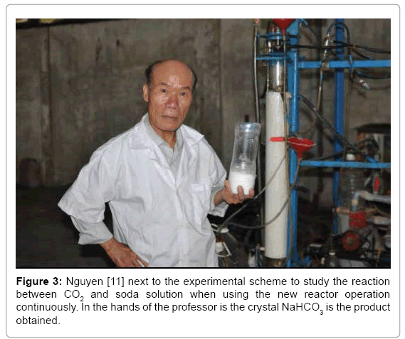
In industry we need new GLSHR continuous operation with extremely high capacity. To achieve this desire we can have enough long shafts and have to rotate with necessary great speed. However in today's industry cannot do that, because conventional stirring shaft is positioned by ball bearing just in the upper part, while the bottom part because in the liquid should not be positioned by ball bearing. We have proposed appropriate measures to overcome the above drawbacks. We created a small compartment at the bottom of the reactor and for regular gas passing through this small compartment, so the bottom part of the stirring shaft usually in dry state and we can positioned ball bearings on the bottom part of the stirring shaft. This way we get GLSHR continuous operation [10]. In Figure 2 Nguyen Dan shows the product crystal NaHCO3 on the hand, which is taking by the new GLSHR continuous operation in the reaction between CO2 and soda liquid on following reaction.

When studying treatment emission line 3.4 million m3/h escape from 1000 MW thermal power plant with coal Fuels, We Know what we can the thousands GLSHR paralleled continuous operation with a diameter 3.5-4 m. This is unenforceable, is too expensive, and combination solutions are suggested the combinations GLSHR [12] on the equilateral triangular principle. Thus we have a Combined GLSHR of 354 individual GLSHR with cross section 3135 m2, for treating exhaust gas flow of 3.4 million m3/h exits from power plants use coal fuel [13]. Use new GLSHR to execute the reaction between CO2 and soda solution. In the Table 1 below the results obtained when carrying out the reaction by new GLSHR [11] (Figure 3). Through this % conversion we see CO2 in the reaction between CO2 and soda solution has risen from 15.96%, while not stir, up 79.4%, while stirring. As such, thanks to stirring with a special structure, which % conversion of CO2 has increased almost 5 times.
| Regime | % CO2 conversion with time (h) | ||||
|---|---|---|---|---|---|
| 0.5 | 1 | 1.5 | 2 | Medium | |
| No stir | 17.41 | 16.77 | 15.48 | 14.2 | 15.96 |
| Stir | 77.15 | 79.47 | 80.8 | 80.2 | 79.4 |
Table 1: Reaction by new GLSHR.
Figure 3: Nguyen [11] next to the experimental scheme to study the reaction between CO2 and soda solution when using the new reactor operation continuously. In the hands of the professor is the crystal NaHCO3 is the product obtained.
Proposed New Technology to Collect Dust Thoroughly and Separation CO2 From Industrial Exhaust Gas
No waste technology for the treatment and reuse industrial exhaust gas
There are hundreds of new technologies in the field of industrial emissions process, we can say that all these technologies has been applied or not implemented industry, has the following disadvantages;
1. These are the technologies with the wastes, and not take reuse wastes of industrial emissions, such as dust, acid oxides in the exhaust stream.
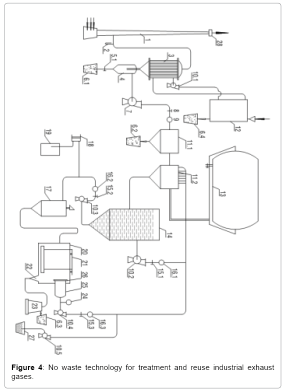
Aims to overcome the above disadvantages, we proposed a new technology, this is no-waste technology, the waste in the industrial emissions, such as dust, nitrogen will be collect and reuse, the technology can be deployed on a large scale to treat industrial waste gas flows out from the thousands of MW thermal power plant using fossil fuels. We know why, so far, the man cannot do the things that desire, because it is only based on the classic devices. We have successfully studied a new generation of devices, and through this new generation of devices, we propose the new technologies as this solution. No-waste technology for treatment and reuse exhaust industrial gases is presented in the following (Figure 4).
Operation of Technology
Emissions from power plants escape outdoor chimney 1. Using gas pump 7 was suck emissions from the chimney 1, then pass through a heat recovery machine 3, coarse dust is separated in 4. Exhaust flow is directed through the speed control valve 8, velocity meter 9, followed to dry dust separator 11.1, to be able to recover almost of the dust in the exhaust stream [1,3,5,7]. The remaining extremely smooth dust and toxic acid oxides will handle by the wet dust separator 11.2 [2,4,6,8]. In this line as soda lye or NaOH is pumping up from pumps 10.2 and 10.4, through flow control valves 15.1, 15.3 and speed meters 16.1 and 16.3. Clean waste gas is recovered after 11.2, will be contained in the bag 13.Containing dust fluid flow is flowing directed into the tank 14, sediment is leading to the bottom of 14 and then in pumping by pump 10.3 for processing and reuse .Suck gas pump 7 was suck emissions from the chimney 1, we improve pumping capacity of 7 so that exhaust velocity control gauge 28, located at the top of the 1, gradually reduced to zero. That is now the whole exhaust no longer escaping from the chimney 1. Regeneration process to fluid that obtained from tank 14 occurs as follows. Liquid pump 10.3 will pump precipitate residue through control valve15.2, then the velocity meter 16.2. Sediment stream will meet flocculation line may be PAC, is pumped up from the metering pump 18, the mixture will be mixed in 17 and overflow continuously to the continuous filtration and sedimentation decant flocculation tank 20 [14]. Here, the precipitate sediment settles to the bottom of the tank, and one way rake 21 raking and recover in the gulf 22, from here, the resulting residue stream is leading continuously to centrifuge decant machine 23, from 23 we obtain moist dust contained in 6.3, then we put the dryer 12 for drying and transparent solution after 23 will be provisional storage in barrel 27, since pump 10.5 will pumps to reuse [14-17]. The fluid steam in the tank 20, after separating the residue will be filtered by the continuous filter 25, to filter out suspended solids in the tank it does not coagulation and precipitate. Pump 10.4 has two functions are the attractive and repulsive is using to enhance the capacity of the filter 26. Here we installed vacuum gauge 24 to monitor the working status of the membrane 26 when the filter clogging, vacuum gauge 24 tells us and rapid process filtration membrane. The liquid is using in tank 20 as soda or washy lye, depending on the required treatment. To ensure stable levels of alkalinity, pH meter was used, and the system provides soda or washy lye.
CO2 Separation New Technology from Industrial Gases N the Kind of Moisture Powder NaHCO3
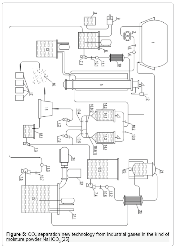
Because liquid CO2 must be stored in expensive high-pressure metal bottles, we take advantage of the ability to form crystal NaHCO3 as product of reaction between CO2 and soda solution under wet powder NaHCO3. We instead the Ethanolamine by cheap soda for CO2 separation, but also capture it in the form of wet powder NaHCO3 entirely without expensive packaging, which could save millions of tons each. Technology (Figure 5) works as follows. Industrial waste gas after it has been thoroughly treated to remove dust and eliminate toxic acid oxides, are contained in bag 1. Emissions from there it is pumping by 2 through valves 3 to meter speed 4, and finally to the bottom new GLSHR 5 [10,12] to conduct a chemical reaction with soda solution is available in 5. Remaining gas after the reaction escaping through the cyclone 12, in order to recover the liquid entrainment. Soda solution was continuously led to 5 as follows. Machine 6 to mix a 20%WP soda solution with the Catalytic, from here by liquid pump 7.1, will pump through control valve 10.1, meter velocity 11.1, then the heat exchanger 19 to maintain temperature 40°C. Lime Soda mixed with a catalyst solution is directed into the top of GLSHR 5.The reaction product is the solution containing NaHCO3 precipitate sludge from the bottom 5 overflowed continuously into 2 decant tanks 14.1 or 14.2. These devices work interruptions, alternately each other; they are equipped with mixer to prevent the early adhesion of the residue in the bottom of the device. Start, for example, the product containing precipitated residue NaHCO3 through the valve 10.2 overflow continuously into 14.1, as well observation liquid level by measuring device 14.3 when we know full scale solution in 14.1,valve 10.2 is locking, and open the valve 10.3 to product flowing through 14.2. Carry handle residue in 14.1. We monitor the NaHCO3 precipitate residue in 14.1, when the sediment was deposited stable, we will open the valve 10.4, and put pump 7.2 to working to pump the sludge from 14.1 to interruption decant centrifugal machine 15 [17] From 15 we get the product wet powder NaHCO3 contained in the bag 17, the liquid after 15 will be stored temporarily in a tank 18.1, then thanks to pump 7.3 injected into storage 18.2 [18]. After the precipitated residue in 14.1 was pumped to the 15, the liquid remaining in the tank 14.1 is pumping to the tank 18.2 by using valve 10.8(2) and liquid pump 7.6. The transparent liquid after the deposition of sediments will be contained in the tank 18.2, in this solution still contain dissolved NaHCO3, this NaHCO3 soluble portion has an adverse effect on the reaction between CO2 and soda solution , if it is not treating heat. The process is conducting as follows. Liquid pump 7.4 will pump this liquid from the tank18.2 through the control valve 10.6 velocity meter 11.2 following to heat exchanger 20, to raise the temperature of the liquid flow from 40°C to 80-90°C by hot soda solution line running from the thermal decomposition furnace 21. After 20, the solution will flow into the thermal decomposition furnace 21, where the NaHCO3 soluble portion will decompose to CO2 was stored in bag 1 and fluid flow is soda solution overflowed continuously through 20 and stored in the tank 22, where is producing 20 %WP soda solution. Soda powder materials contain in bunker 23, loading screw and motor 24 push continually powder soda to 22, thanks to hydrometer 22.1, which we can observe the process of preparing the soda solution for the technology. Standard soda solution from tank 22 is pumping by the pump 7.5 through control valve 10.7, speed meter 11.3 to device 6 for mixing with catalyst.
Figure 5: CO2 separation new technology from industrial gases in the kind of moisture powder NaHCO3 [25].
Reaction temperature of 40°C will be maintained by automatic thermostat 13. Heat load is pumping into the casing of GLSHR 5.
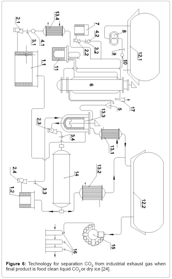
New technology for separation CO2 from industrial exhaust gas when final product is food clean liquid CO2 or dry ice [19]
The technology is shown in Figure 6. The industrial exhaust gas is treated thoroughly to separate the industrial dust as well as treatment the toxic acid oxides, which is containing in the bag 12.1. Thanks the screw pump 8 gas is pumping through the control valve 9, the speedometer 10 and finally injects into the bottom of GLSHR 6 [10,12] to carry out the chemical reaction with the existing soda solution in 6. Gas after 6 escapes through the cyclone 17 to recover the rolling fluid. The soda solution is introducing into 6 as follows. From Storage tank 1.1 20% WP soda solution is pumping by liquid pump 2.1 through control valve 3.1, velocity meter 4.1, then to the heat exchanger 13.4 to maintain temperature 40°C, next, this solution will encounter catalytic solution, catalyst solution from tank 7 is pumping by pump 2.2, through control valve 3.2, speedometer 4.2.
Figure 6: Technology for separation CO2 from industrial exhaust gas when final product is food clean liquid CO2 or dry ice [24].
Mixture of soda solution with the catalyst introduced into the top of the new GLSHR 6. The reaction product is a solution of NaHCO3 precipitated, flowing continuously from bottom 6 into funnel 5 to enter the heat exchanger 13.3, where the hot soda solution stream in the Temperature of 100-102°C transfers heat to the solution stream containing precipitated NaHCO3 from the reactor 6, temperature at 40°C, it is brought to 55-60°C, the device is stirred vigorously and here NaHCO3 decomposition begins as follows

CO2 collects after passage reverse cold machine 13.1 will be collected in air bag 12.2, after 13.3, the remaining solution after decomposition also contains a portion of NaHCO3 solution, thank the liquid pump 2.3 will pump directly into rotary kiln for the thermal decomposition [20], the temperature in the rotary kiln is maintaining at 102-103°C, which is the boiling point of the 20% WP soda solution. From the furnace, the CO2 stream obtains after the reverse cold machine 13.2, will enter into the air bag 12.2, the hot soda solution, flows out continuously and is preserving in the reservoir 1.2, from which liquid pump 2.4 will pump it into the heat exchanger 13.3. Finally, the recycled soda solution is stored in the original tank 1.1 containing 20% WP soda solution. The 4-stage high-pressure pump 15 draws CO2 from the air bag 12.2 and liquefies the CO2, which is contained in high-pressure metallic bottles 16 or can be turned into dry ice in suitable packaging [21-25].
Conclusion
The successful introduction of dry and wet separators makes fully industrial dust treatment possible. Most of the dust is separated in the dry state by a dry dust separator, while the remainder is Extremely smooth dust particles along with acid oxides will treat with a wet dust extractor. These dust separators meet industrial requirements of any size we require. So far no completed industrial solid-liquid gas heterogeneous reactors exist. With new inventions of new types of reactors for gas-solid-liquid heterogeneous systems such as liquidliquid, liquid-gas, liquid-solid, solid-liquid-gas, these new reactors can make significant changes for the chemical industry, petrochemicals, food chemistry. These new reactors can operate intermittently, or continuously, and especially when assembled, they provide a very large scale to satisfy the large industrial requirements. From the new equipment above, we will have complete technologies to handle the principle of zero emissions and CO2 recovery from industrial emissions as moisture powder NaHCO3 or liquid CO2 or dry ice.
References
- Nguyen D (2013) Upgrade dry-cyclone dust separator. Patent no.: 1-2013-02643.
- Nguyen D (2013) Upgrade wet cyclone dust separator. Patent no.: 1-2013-02732.
- Nguyen D (2013) Combined upgrade dry cyclone dust separator. Patent no.: 1-2013-02730.
- Nguyen D (2013) Combined upgrade wet cyclone separator. Patent no.: 1-2013-02732.
- Nguyen D (2013) Dry centrifugal cyclone dust separator. Patent no.: 1-2013-02690.
- Nguyen D (2013) Wet centrifugal cyclone dust separator. Patent no.: 1-2013-02691.
- Nguyen D (2014) Dry filtered centrifugal dust separator. Patent no.: 1-2014-01960.
- Nguyen D (2014) Wet filtered centrifugal dust separator. Patent no.: 1-2014-01961.
- Nguyen D (2013) Interruption new gas liquid solid heterogeneous reactor (GLSHR) Patent no.: 1-2013-02639.
- Nguyen D (2013) The combined Interruption GLSHR. Patent no.: 1-2013-03146.
- Nguyen D (2013) Combined continuous new GLSHR. Patent no: 1-2013-02728.
- Nguyen D (2013) Vertical continuous centrifugal decanting machine. Patent no.: 1-2013-02638.
- Nguyen D (2013) Vertical interruption centrifugal decanting machine. Patent no.: 1-2013-02638.
- Nguyen D (2013) Filter membrane cleaning machine. Patent no.: 1-2013-02692.
- Nguyen D (2013) CO2 separation technologies from industrial emissions under form of food clean liquid CO2 or dry ice. Patent no.: 1-2013-02881.
- Nguyen D (2013) Dry and wet sinusoidal dust separator. Patent no.: 1-2013-02642.
- Nguyen D (2013) Multi-layered solution for the new GLSHR. Patent no.: 1-2013-02727.
- Nguyen D (2013) Continuous filtration and sedimentation flocculation tank. Patent no.: 1-2013-02729.
- Nguyen D (2013) No-waste technology for the treatment and reuse industrial exhaust gas. Patent no.: 1-2013-02883.
- Nguyen D (2013) CO2 separation technologies from industrial emissions under form of food clean liquid CO2 or dry ice. Patent no.: 1-2013-02881.
- Nguyen D (2013) CO2 separation technology from industrial exhaust gas in the form of moisture powder NaHCO3. Patent no.: 1-2013-02882.
Citation: Nguyen D (2018) To Overcome the First Disadvantage in the Fight against Global Climate Change, which Suggest New Generation Equipment and Needed New Technologies. Environ Pollut Climate Change 2: 146. DOI: 10.4172/2573-458X.1000146
Copyright: © 2018 Nguyen D. This is an open-access article distributed under the terms of the Creative Commons Attribution License, which permits unrestricted use, distribution, and reproduction in any medium, provided the original author and source are credited.
Select your language of interest to view the total content in your interested language
Share This Article
Recommended Journals
Open Access Journals
Article Tools
Article Usage
- Total views: 4473
- [From(publication date): 0-2018 - Aug 02, 2025]
- Breakdown by view type
- HTML page views: 3619
- PDF downloads: 854

