Research Article Open Access
Whispering Gallery Microcavity Nanosensor with In-Line Interferometer
Steven Herchak, Wenyan Yu, Wu-Sheng Lu and Tao Lu*
Department of Electrical and Computer Engineering, University of Victoria, Canada
- Corresponding Author:
- Lu T
Department of Electrical and Computer Engineering
University of Victoria, Victoria
BC V8P 5C2, Canada
Tel: +12507217211
E-mail: taolu@ece.uvic.ca
Received Date: June 21, 2015 Accepted Date: August 19, 2015 Published Date: August 21, 2015
Citation: Herchak S, Yu W, Lu WS, Lu T (2015) Whispering Gallery Microcavity Nanosensor with In-Line Interferometer. Biosens J 4:122. doi:10.4172/2090- 4967.1000122
Copyright: © 2015 Herchak S, et al. This is an open-access article distributed under the terms of the Creative Commons Attribution License, which permits unrestricted use, distribution, and reproduction in any medium, provided the original author and source are credited.
Visit for more related articles at Biosensors Journal
Abstract
Here we demonstrate a simple but robust interferometry scheme that connects an ultra-high quality factor whispering gallery micro cavity to a FC/PC connectorized single mode fibre. With this scheme, single Polystyrene beads with a radius as small as 25 nm can be detected at a signal-to-noise ratio of around 3.
Keywords
Interferometer; Microcavity nanosensor; Whispering gallery mode
Introduction
The application of whispering gallery mode (WGM) microcavities for Nano detection and biosensing is a field of research seeing ongoing attention [1-15]. This method exploits the high quality-factor (Q) of the optical cavity for ultra-sensitive monitoring of shifts in the resonant wavelength. These resonant wavelength shifts are due to modifications in the optical properties of the resonator that can be due to the binding of individual nanoparticles or molecules. The typical procedure for monitoring the resonant wavelength of a microcavity includes scanning a tuneable wavelength laser while photo detecting the optical transmission which is monitored on an oscilloscope [3]. One issue with this method is the inherent uncertainty in the location of the transmission dip due to fluctuations in the laser wavelength, known as laser jitter. To circumvent this issue the use of an interferometer to produce a reference signal that follows the laser jitter has been used with an observed increase in sensitivity [10]. The demonstrated scheme, however, requires a split-off of the probe laser to the interferometer. This limits its application to power sensitive measurement where the maximum injection of probe laser power into the cavity is required. Here, we report that by simply inserting a FC/PC connectorized fibre as a Fabry P´erot (FP) interferometer (FPI) after the output of a whispering gallery cavity, one may reach similar detection sensitivity as reported in ref. [10] with a much simpler setup and without the necessity of split-off power.
Serial Mach-Zehnder Interferometer
In our first experiment, we connected a fibre Mach-Zehnder interferometer (MZI) in serial to the WGM sensor as shown in Figure 1a. A 630 nm central wavelength probing laser is fed with a frequency modulating ramp signal from a waveform generator. Then the power from the laser is sent through a polarization controller and subsequently enters a region of fibre optic taper. In the tapered region of the optical fiber a microsphere is brought into proximity with a piezoelectric Nano positioning device so optical coupling occurs. The power transmitted from the microsphere is fed to a thermally and mechanically stabilized MZI. The two output ports of the interferometer are detected by a balanced amplified photo detector (PD) upon being monitored by an oscilloscope.

Figure 1: Experiment setup.
Through scattering matrix techniques, one may easily derive that the output signal received at the photodetector V(v) at probe laser frequency v follows
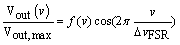 (1)
(1)
where Vout,max is the maximum voltage, ΔvFSR the free spectral range of the interferometer and f(v) the micro cavity transfer function expressed as
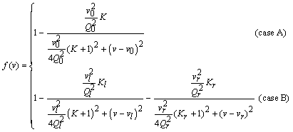 (2)
(2)
Where in the absence of mode splitting [16] (case A), f (v) has a single Lorentzian shape with Q0, the intrinsic Q of the cavity, v0 the cavity resonance frequency and K =Q0/Qc the normalized coupling parameter defined as the ratio of the intrinsic Q and coupling Q (Qc). In the presence of mode splitting (case B), f (v) displays a double Lorentzian structure with two dips centred at vl and vr corresponding to the cavity resonance frequency of the cosine and sine mode. Note through a least square fit procedure applied to Eq. 1, one may track the shift of cavity resonance wavelength upon particle binding. To validate our scheme, we first perform a numerical simulation on the system with the modelling parameters listed in Table 1. In Figure 2, we first constructed the transmitted signal in our model (blue dots) and conducted a least square fit (LSF).

Figure 2: Serial MZI simulation and LSF results.
| Parameter | Value |
|---|---|
| Resolution | 40 ns |
| Total Q | 5 × 10⁷ |
| Resonant Wavelength | 635.5 nm |
| FSR | 36.1 MHz |
| Signal Amplitude | 1 V |
| Scan Rate | 1.0 × 10¹² Hz/s |
| SNR | 25 |
Table 1: Serial MZI simulation parameters.
With Eq. 1 As shown, the fitted curve is in excellent agreement with the signal.
It is noted that there is a loss of information if the resonant wavelength of the microcavity is in proximity to the MZI sinusoidal zero point. This problem is apparent from Figure 3 where there is a clear jump in the resonant wavelength error near the point Δv=15 MHz. This location was confirmed to be the location of the sinusoidal zero point by both plotting the phase angle corresponding to the location of the resonant dip, and plotting the simulated data at this point. Because of this zero point, the sensing limitation of the MZI for a system with physical parameters given in Table 1 is for resonant wavelength shifts that can be detected with a 0.94 fm 3σ uncertainty. Therefore, although the employment of a balanced photo detector is favourable for Mach- Zehnder interferometry to cancel the excessive intensity noise, it is not suitable in this application as the output signal is bi-polar. To further overcome the inaccuracy occurred at quadrature points and simplify our setup, we adopt a simple Fabry-P´erot interferometer (FPI) scheme in the following section.

Figure 3: Serial MZI simulation resonant wavelength error.
Serial Fabry-Pe´rot Interferometer
The serial FPI set-up is shown in Figure 1b, which is identical to the previous scheme except that the MZI is replaced by a FPI and the transmitted signal is measured by a photodetector (PD). Here, the FPI is simply a fiber patch cord with (FC/PC) connectors on both ends. The connectors are not completely tightened so that a small portion of the light may back reflect between the connectors to form a FP type interferometer. It is also worth noting that in a typical micro cavity sensing system, an inherent FP cavity may already exist due to, eg. The minute back-reflection from poorly cleaned fiber connectors, which usually introduce sinusoidal ripples in the transmission spectrum. Therefore, one may use the following approach to improve the sensing resolution without introducing any new components in his setup.
Following similar derivations to the MZI, the output signal Vout (v) can be expressed as
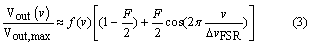
Here due to the small reflectivity at the connector air interface, the finesse F is much less than unity. Therefore we can approximate the Airy function from the FPI transfer function [17] to the sinusoidal form above for simplicity. Again, with a least square procedure, one may track the cavity resonance shift from the particle binding events. For the validation purposes, the LSF was performed on data simulated with Eq. 3 using the physical parameters listed in Table 2. The fit is compared to simulated data in Figure 4, and the resonant wavelength error is displayed in Figure 5. As shown in contrast to the MZI case discussed in previous section, the FPI yields uniform estimation inaccuracy regardless the value of the cavity resonance wavelength.

Figure 4: Serial FPI simulation and LSF results.

Figure 5: Serial FPI simulation resonant wavelength error.
| Parameter | Value |
|---|---|
| Resolution | 80 ns |
| Total Q | 5 × 10⁷ |
| Resonant Wavelength | 635.5 nm |
| FSR | 49.6 MHz |
| Signal Amplitude | 1 V |
| Scan Rate | 1.0 × 10¹² Hz/s |
| Coefficient of Finesse | 0.251 |
| SNR | 25 |
Table 2: Serial FPI simulation parameters.
Experimental Results
To verify the FPI approach, we setup sensing experiments according to Figure 1b. Here we use a silica microsphere immersed in Dulbecco’s Phosphate-Buffered Saline (DPBS) as nanosensor and the FPI has a ΔvFSR=49.8 MHz. As shown in Figure 6, the LSF of the transmission spectrum indicates that our probe laser frequency scanned at a rate of 2 × 10⁶ MHz/s as one period of sinusoidal ripple found in the spectrum represents an optical frequency change of one free spectral range. Correspondingly, the Q of the cavity is obtained to be 2.1 × 10⁸ through the same fitting procedure. We further collected 8192 transmission traces from the oscilloscope and displayed as a spectrogram in Figure 7. In our experiment, we triggered our oscilloscope near the bottom of the signal dip, which sets the resonance dip at the same time slot on the spectrogram. As shown in the figure, the optical frequency of sinusoidal ripples drifted up relative to the cavity resonance, indicating a slow decrease of cavity resonance frequency or equivalently increases of resonance wavelength. This is anticipated due to the slow drifting of both the ambient temperature and the gap between the fiber taper and the cavity. Nevertheless, the resonance wavelength drift of less than 10 fm over 80 seconds as shown by the blue trace extracted from the spectrogram through LSF procedure in Figure 8 indicates that our sensing setup is highly stable for the detection of resonance wavelength steps produced by nanoparticle binding events. Also as a comparison we track the cavity resonance wavelength through the conventional method where the probe laser frequency modulation voltage at the cavity resonance dip was recorded to estimate the resonance wavelength. As shown (grey trace), the conventional method yields a measurement uncertainty of around 17 fm whilst our FPI reduced the uncertainty by more than an order of magnitude to around 1 fm. In addition, the conventional method indicates a larger cavity resonance wavelength drift compared to the FPI measurement result. That is due to the fact that wavelength wander occurs in probe lasers. Consequently, the conventional method produced a systematic error in estimating the cavity resonance wavelength shift while such error does not exist in interferometry systems.
In the following experiment, we injected 25 nm polystyrene Nano beads in the buffer. As shown in Figure 9, due to the increased backscattering from the adsorbed Nano beads, mode splitting was observed in the transmission spectrogram. The shift of split frequency due to the binding events at 3.1 second was evident from the spectrogram. We further applied our LSF procedure in combination to a step finder to the spectrogram. As shown in Figure 10, at 3.1 second, a cavity resonance wavelength shift in an amount of 1.6 ± 1.0 fm was observed at the left resonance dip while a step of 3.1 ± 0.9 fm was observed at the right resonance dip. Equivalently, this is an average resonance wavelength shift of 2.4 fm and a mode splitting wavelength shift of 1.5 fm due to the binding event.

Figure 6: Serial FPI experimental data with fitting results.

Figure 7: Transmission spectrogram.

Figure 8: Serial FPI experimental results in buffer.

Figure 9: Transmission spectrogram of the 25-nm-radius polystyrene nanobeads binding events.

Figure 10: Left resonance wavelength shift due to the binding.
Step finding algorithm
An algorithm for detecting steps from noisy resonant wavelength samples is demonstrated here. Discrete samples were collected as a trace of the resonant peak positions (grey dotted lines in Figures 10 and 11) which themselves were identified by least squares fitting. Because of the presence of noise, a de-noising procedure turned out to be necessary before numerical differentiation can be applied to the data. The denoising consists of two steps: first a median filter [18] was applied to smooth the noisy data in question and remove possible outliers (blue traces in Figures 10 and 11). To further reduce the noise, a de-noising technique based on total-variation minimization was further applied [19] (red traces in Figures 10 and 11), which is known for its ability to reduce random noise while preserving signal edges (i.e., steps in the present case). Numerical differentiation was then applied to the processed data and a total of N locations with the largest derivatives were picked as candidate step locations. Finally, least squares fitting were applied to fit the data at these possible step locations into a step function and the corresponding SNR was evaluated. A step was deemed to occur if the SNR exceeded a predetermined threshold which was set to one in this case.

Figure 11: Right resonance wavelength shift due to the binding.
Conclusion
The reference interferometry technique is a versatile sensitivity enhancing element in Nano detection experiments. The serial connected interferometer approach was shown to be of benefit. This was achieved by carrying out an experiment with a FPI in line with a microsphere of loaded Q 2.1 × 10⁸. The mean sensitivity of this experiment was 1 fm, showing an increase of 20 times improvement over the conventional sensitivity.
Although the in-line FPI approach shows slightly larger measurement uncertainty compared to that of the parallel MZI approach [10] due to the fact that no thermal stabilization to the FPI was adopted here, the simplicity of using a fibre patch cord -or even directly using the inherent FP cavity- makes the FPI an intriguing technique. Beyond simplicity, the FPI technique has been shown to improve resolution by an order of magnitude.
Acknowledgements
The author would like to thank Xuan Du for helping create the figures depicting the experimental set-up. This work was supported by the Natural Sciences and Engineering Research Council of Canada.
References
- Arnold S, Khoshsima M, Teraoka I, Holler S, et al. (2003) Shift of whispering-gallery modes in microspheres by protein absorption. Optics Letters 28:272-274.
- Vollmer F,Braun D, Libchaber A, Khoshsima M, Teraoka I, et al. (2002) Protein detection by optical shift of a resonant microcavity. Applied Physics Letters 80: 4057-4059.
- Vollmer F, Arnold S(2008) Whispering-gallery-mode biosening: label-free detection down to single molecules. Nature Methods 5: 591-596.
- Fan X, White IM, Shopova SI, Zhu H, Suter JD, et al. (2008) Sensitive optical biosensors for unlabeled targets: A review. Anal ChimActa 620: 8-26.
- Kim KH, Bahl G, Lee W, Liu J, Tomes M et al. (2013) Cavity optomechanics on a microfluidic resonator with water and viscous liquids. Light: Science & Applications 2:e110.
- Lee MR, Fauchet PM (2007)Nanoscalemicrocavity sensor for single particle detection. OptLett 32: 3284-3286.
- Min B, Ostby E, Sorger V, Ulin-Avila E, YangL, et al. (2009) High-Q surface plasmonpolariton whispering gallery microcavity. Nature 457: 455-458.
- Dantham VR, Holler S, Barbre C, Keng D, KolchenkoV, et al. (2013) Label-free detection of single protein using a nanoplasmonic-photonic hybrid microcavity. Nano Letters 13:3347-3351.
- Baaske MD, Foreman MR, Vollmer F (2014) Single-molecule nucleic acid interactions monitored on a label-free microcavity biosensor platform. Nature Nanotechnology 9: 933-939.
- Lu T, Leea H,Chena T, Herchakb S, Kim JH, et al. (2011) High sensitivity nanoparticle detection using optical microcavities. Proceedings of the National Academy of Sciences 108: 5976-5979.
- Liu F, Alaie S, Leseman ZC, Hossein-Zadeh M (2013) Sub-pg mass sensing and measurement with an optomechanical oscillator. Opt Express 21: 19555-19567.
- Yu W, Jiang WC, Lin Q, Lu T(2014) Coherent optomechanical oscillation of a silica microsphere in an aqueous environment. Opt Express 22: 21421-21426.
- Lu T, Su TTJ, Vahala KJ, Fraser S (2008) Split frequency sensing methods and systems. US Patent, US20100085573 A1
- Zhu J,Ozdemir SK, Xiao YF, Li L, He L, et al. (2010) On-chip single nanoparticle detection and sizing by mode splitting in an ultrahigh-Q microresonator. Nature Photonics 4: 46-49.
- Knittel J, McRae TG, Lee KH, Bowen WP (2010)Interferometric detection of mode splitting for whispering gallery mode biosensors. Applied Physics Letters 97: 1-3.
- Gorodetsky ML, Pryamikov AD, Ilchenko VS (2000) Rayleigh scattering in high-Q microspheres. Journal of Optical Society of America B 17: 1051-1057.
- Born M, Wolf E (1980) Principles of Optics. (6thedn), PergamonPress Ltd., London.
- Arce GR (2005) Nonlinear Signal Processing: A Statistical Approach. John Wiley & Sons, New York.
- Beck A,Teboulle M (2009)Fast gradient-based algorithms for constrained total variation image denoising and deblurring problems. Image Processing, IEEE Transactions on 18: 2419-2434.
Relevant Topics
- Amperometric Biosensors
- Biomedical Sensor
- Bioreceptors
- Biosensors Application
- Biosensors Companies and Market Analysis
- Biotransducer
- Chemical Sensors
- Colorimetric Biosensors
- DNA Biosensors
- Electrochemical Biosensors
- Glucose Biosensors
- Graphene Biosensors
- Imaging Sensors
- Microbial Biosensors
- Nucleic Acid Interactions
- Optical Biosensor
- Piezo Electric Sensor
- Potentiometric Biosensors
- Surface Attachment of the Biological Elements
- Surface Plasmon Resonance
- Transducers
Recommended Journals
Article Tools
Article Usage
- Total views: 15193
- [From(publication date):
December-2015 - Aug 16, 2025] - Breakdown by view type
- HTML page views : 10093
- PDF downloads : 5100