Harnessing Low Power Wind Energy from Riverine and Isolated Potential Pockets using Wound Rotor Induction Machines
Received: 06-Sep-2012 / Accepted Date: 19-Mar-2013 / Published Date: 22-Mar-2013
Abstract
At present the harnessing of the wind energy is focused at highly potential wind sites where the average wind speed is high (>7m/s). However, in many undeveloped and even developing countries, there is no electrical power supply at all or there is no regular electrical power supply in vast areas. For example, in India, there are more than 80,000 villages which are still not connected to electrical power grid and connection of 18,000 remote villages are not commercial viable. Furthermore, there is 27% average power loss in the transmission and distribution lines. The situations in African and many South-East Asian counties are not much different. Therefore, generation of electrical power locally, and preferably from the renewably energy sources which do not pollute the atmosphere, is a viable solution. There are some geographical conditions and topology (landscape) which cause acceleration in wind speed. It includes crest of a hill, funnel effect and ridge oriented perpendicularly. The wind energy available at such locations can be harnessed. In this work, the plain of Ganges basin is selected for this purpose due to high pollution and the power demand of the region. The river becomes wide, forms several kilometer wide small and wide islands at different locations between Moradabad to Bhagalpur. It resembles a narrow bay of sea and due to this type of typical topography (like sea and coast), the wind speed increases at such riverine. Moreover, some potential locations are also found which were not spotted by satellite imaging. For harnessing the low wind power, both grid-tied and stand alone and schemes using wound-rotor induction generators are proposed. Both systems are tested successfully.
Keywords: Wind Energy Conversion System (WECS); Low wind speed; Pollution; Climate change; Induction generator; Stand-alone generation; Grid-tied generation
10405Introduction
The surface of the earth is not homogeneous. It absorbs the solar energy radiation differently which creates difference in atmospheric temperature [1]. Thus the density and pressure of air also change which in turn move the air from one place to another. Therefore, the land and water along coast line, valleys and mountains create breezes [2]. The wind power is proportional to cube of the wind speed. At present the harnessing of the wind energy is focused at highly potential wind sites where the average wind speed is high (>7 m/s). New wind farms (MW range) are coming up in these areas from Multi-National Companies (MNC) because these sites are profitable and commercially viable. Thus the wind turbines are not installed and wind energy is not harnessed where the wind speed is low. However, in many undeveloped and even developing countries, there is no electrical power supply at all or there is no regular electrical power supply in vast areas. For example, a large number of people (300 million out of 1.2 billion) are not getting electrical power facility in India [3]. There are more than 80,000 villages which are still not electrified. Moreover, it is not commercial viable to connect 18,000 remote villages to the national power grid. The situation in African and many South-East Asian counties are not different. The non-availability of electric power forces the use of burning of fossil fuel which is already causing environment pollution in Asian countries as shown in Figure 1 [3].
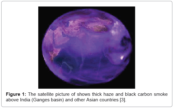
Figure 1: The satellite picture of shows thick haze and black carbon smoke above India (Ganges basin) and other Asian countries [3].
Furthermore, there are 10% and 27% average power loss in the transmission and distribution lines in developed countries and in India, respectively [4]. In addition to higher tariff (higher rate), it causes power wastage on continuous basis which leads to environmental heating and climate change [3]. Therefore, the generation of electrical power locally to save transmission and distribution losses, and preferably from the renewable energy sources which do not pollute the atmosphere, is a viable economical solution. It may be noted that these remote areas are not attractive commercial investment sites. The energy demand in developing and undeveloped countries is low which restricts to lighting, mobile/cell phone charging, refrigeration and water pumping applications. Therefore, instead of bulk power generating systems, large number of low-power renewable energy systems including wind turbines may be used. It may fulfill the power needs of remote areas as well as the surplus power may be supplied to nearby power grid, if available. Most of the population of world is settled at the bank of rivers and in river plains (riverine). Often these areas are away from sea coast with little wind power. However, there is a silver lining that some geographical conditions and topology cause acceleration in wind speed [2]. It includes
(i) crest of a hill with shape feature as convex
(ii) funnel effect between two cliffs or ridge
(iii) ridge oriented perpendicular to the wind direction
Thus substantial electric power may be generated using the accelerated wind. Figure 2 shows the geographic conditions which accelerate the wind speed locally. However, the standard source of the information for wind map has poor resolution (e.g. Google wind map, satellite based data maps etc.) [5]. It does not cover the local effects which accelerate the wind locally and therefore satellites or remote sensing equipment does not spot it. When big rivers (Amazon in Brazil, Ganges in India etc.) pass through plain, they follow spiral path, make islands and become several kilometer wide. It resembles a narrow bay of sea and due to this type of typical topography (like sea and coast), the wind speed increases at such riverine which can be harnessed. There is a significant scope to harness the energy in low wind areas using large number of low wind power turbines.
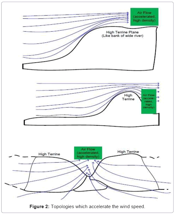
Figure 2: Topologies which accelerate the wind speed.
The wind map provided by Google or Agency of Government of India (Centre of Wind Energy Technology, CWET) [5], does not show any significant potential of wind energy in the whole of the plain of north India, as shown in Figure 3. However, some potential sites are found in hilly and mountain areas which can be correlated using map shown in Figure 4 (plains are shown by green colour). In the present work, the feasibility of harnessing the wind energy from isolated pockets, Ganges basin and riverine is explored. It is already established that the Ganges basin has high level of pollution. Therefore apart from pollution control it will help rural development.
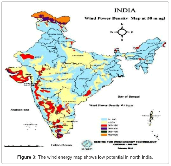
Figure 3: The wind energy map shows low potential in north India.
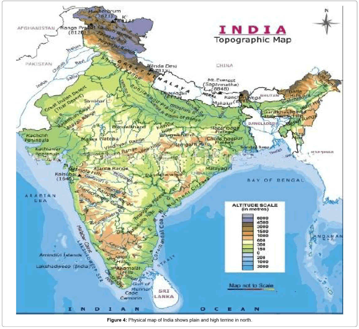
Figure 4: Physical map of India shows plain and high terrine in north.
In this work, the plain of Ganges basin is selected for exploring the potential wind energy pockets and different locations where substantial wind power is available due to local factors and where the low power wind turbines can be installed. Therefore, the pollution of the region will be reduced and substantial energy demand can be fulfilled. For harnessing the low wind power, both stand alone and grid-tie schemes are also proposed using a wound-rotor induction machine in standalone mode working as an alternator as well as in a grid tied system. Both systems are tested successfully.
Potential Wind Areas
As discussed in previous section, there are various conditions which accelerate the wind speed locally. On the basis of that the potential wind energy area is explored. In this work, the crest of a hill, convex type landscape and bank of a wide river are used to search the potential area. The physical or satellite map shows that near the plain of Ganges basin, there are high terrines nearby (southern part of the basin, shown by yellow and brown colours in Figure 4). Similarly, it is evident from Google-map that the river is wide at several places due to island formation as shown in Figure 5 [5]. Moreover, it can also be established by the wind and cyclone hazard map that these areas (Ganges basin) experience wind hazards i.e. high wind speed (Figure 6). Therefore there is always a chance of some potential wind sites in this region. Thus the potential wind energy area is found in plain of Ganges basin which stretches from Moradabad to Bhagalpur.
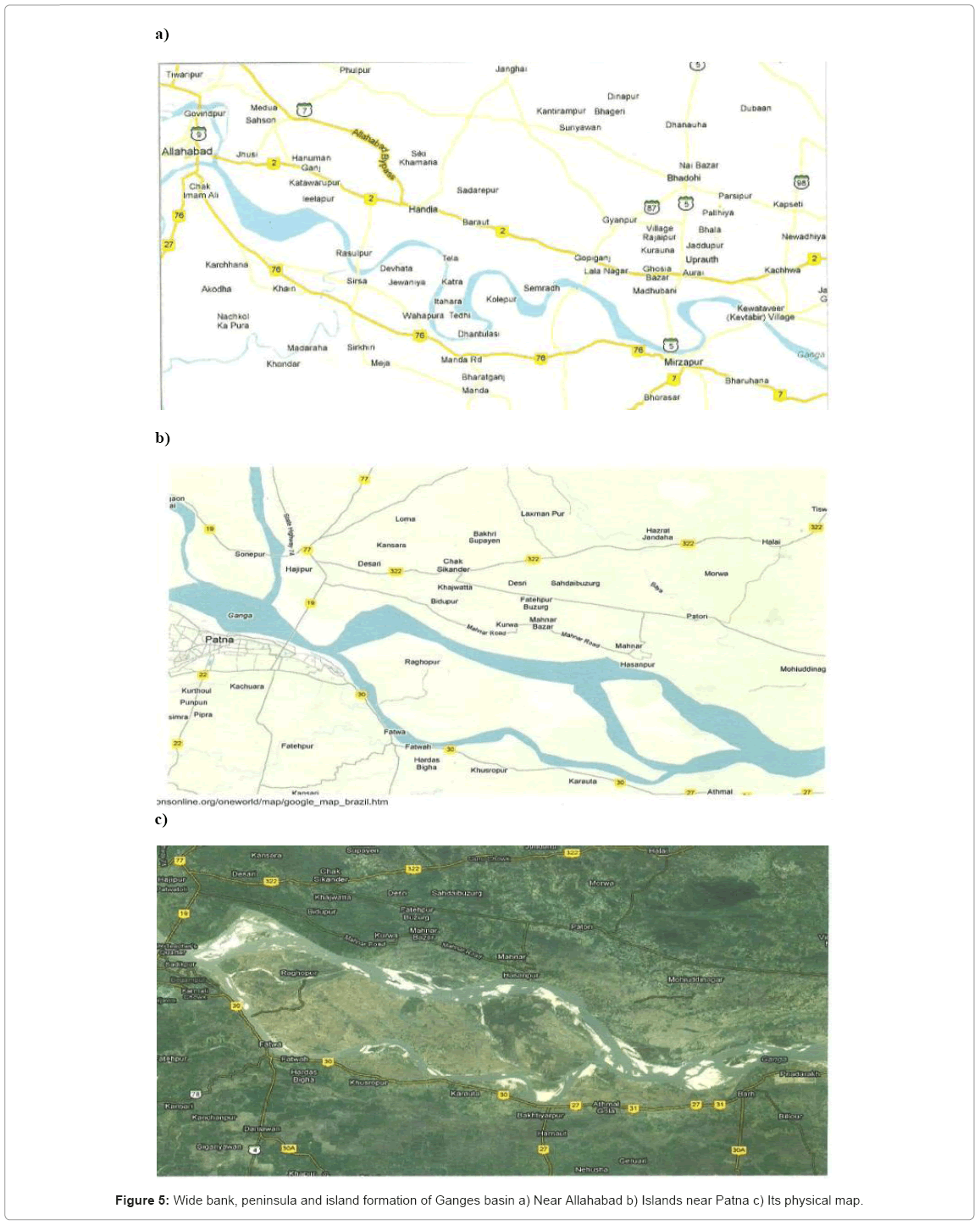
Figure 5: Wide bank, peninsula and island formation of Ganges basin a) Near Allahabad b) Islands near Patna c) Its physical map.
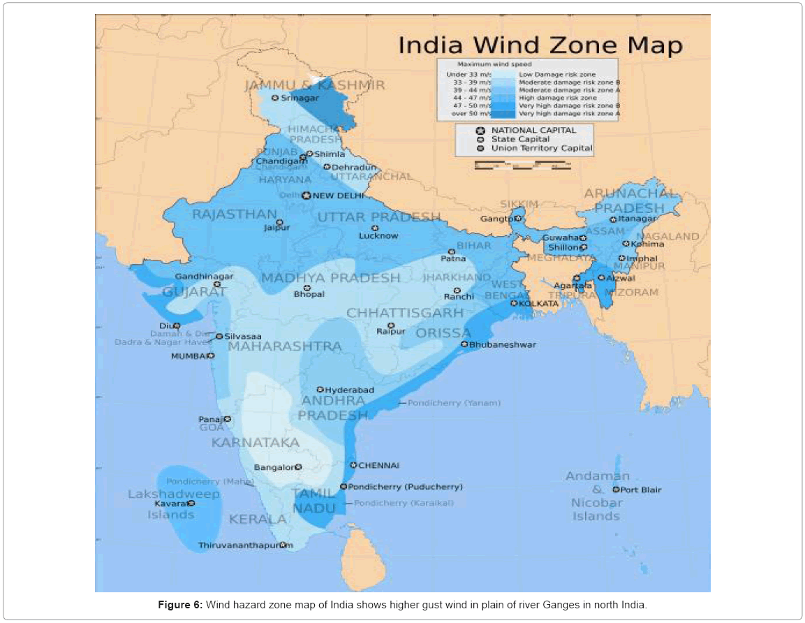
Figure 6: Wind hazard zone map of India shows higher gust wind in plain of river Ganges in north India.
In the plain, the river flows eastward (not southward), forms peninsula and becomes wide, forms several kilometer wide small and wide islands in the plain. The average wind speed is found higher than that of the adjacent area shown in the map provided by CWET [5]. It is interesting to note that people are living in these flood-prone areas without availability of electricity. Moreover, many locations are not far off from urban area or power grid line. The surplus harnessed power can also be supplied to grid or alternatively a short distance line may be used to link the power grid. Thus large number of low wind power systems can be installed and even the generated power can be fed to grid.
The month of April is a calm month in North India with least wind speed. In this month, high wind speed (average= 5.5 m/s) is found at one of the island (Figure 5(c)) of Ganges near Patna. However, contrary to that low wind speed (average=3 m/s) is found at the bank of the same river at Varanasi. It is evident from Figure 7 that there is no island and the same river is not wide near Varanasi.
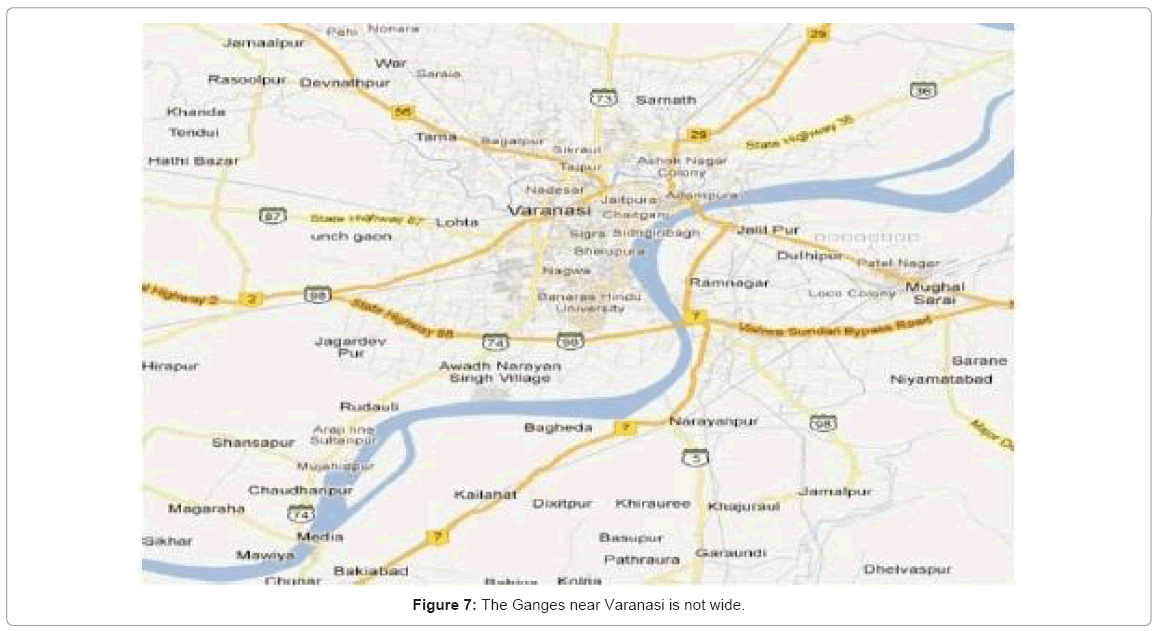
Figure 7: The Ganges near Varanasi is not wide.
Physical Locations and Landscape
As discussed in the first section, the physical locations also accelerate the wind speed. Therefore similar locations may be searched to find the potential wind energy sites for installation of small wind turbines. The high slopes (landscape) and rooftop of isolated buildings resemble the similar physical conditions, as explained in Introduction (section 1).
For a potential slope, first of all the most likely direction of wind has to be established i.e. mostly wind flows in what particular direction? Then the slope should be favorable i.e. rising. For Aligarh, the normal wind direction is North-west. It is established by the statistics available of the nearby places [6], i.e. Agra and New Delhi Airport which are at 100 km and 150 km, respectively (Figure 8). A house is selected for this purpose which lies at slope and has a landscape as shown in Figure 9. The rooftop of the house had higher wind (3 m/s) while at the ground it was only 1.3 m/s, when the direction of wind is favourable. It may be noted that at the same place when the direction of wind was opposite i.e. eastward (not favourable), for a higher wind at the ground (1.6 m/s), the speed at the rooftop was only 2.5 m/s (lower than previous case).
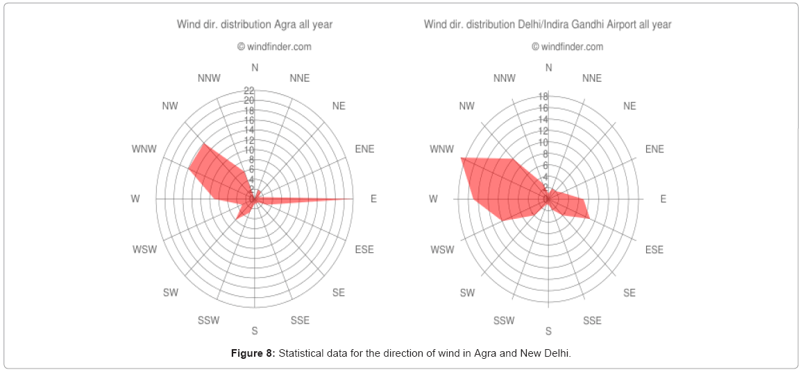
Figure 8: Statistical data for the direction of wind in Agra and New Delhi.
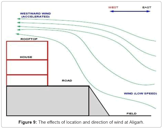
Figure 9: The effects of location and direction of wind at Aligarh.
Similarly, at rooftop of an isolated building (Figure 10), it has convex type structure as discussed in Introduction. Thus a higher wind speed is found irrespective of the direction of wind. When the wind speed was 2.9 m/s at ground, it was 5.1 m/s at the rooftop.
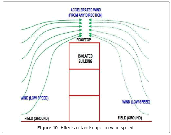
Figure 10: Effects of landscape on wind speed.
Wind Energy Electrical Power Systems
For low power Wind Energy Conversion System (WECS), Permanent Magnet (PM) synchronous machine is used as a generator or an alternator. Its output has variable voltage as well as variable frequency which depend upon the speed of the turbine [2]. However, due to PM it is costlier and due to variable frequency it cannot feed power to electrical grid directly. The output ac voltage has variable frequency which is converted into dc using a rectifier circuit. The dc output is again converted into a constant (mains) frequency ac, using a grid-tied inverter and fed to grid. However, a grid connected constant speed cage-type Induction Generator (IG) is preferred over a synchronous generator due to lower cost, ruggedness and the requirements of less maintenance [7,8]. No separate inverter or synchronizing circuits are needed and the ac grid voltage itself regulates the frequency and output voltage of IG (Figure 11). The IG operates at 1% slip by gear and pitches control. But in this case, a significant power is wasted at high wind speed as the wind power is cube of wind speed. Therefore, a slight increase in wind speed causes great jump in wind power. Normally, the gearbox of a wind turbine has single gear ratio between the rotation of the rotor and the induction generator. Therefore, either the control has to be applied on pitching the rotor blades out marginally or fully as required (mechanical control), or on the generator (electrical control). However, an electrical control is highly efficient and reliable [8].
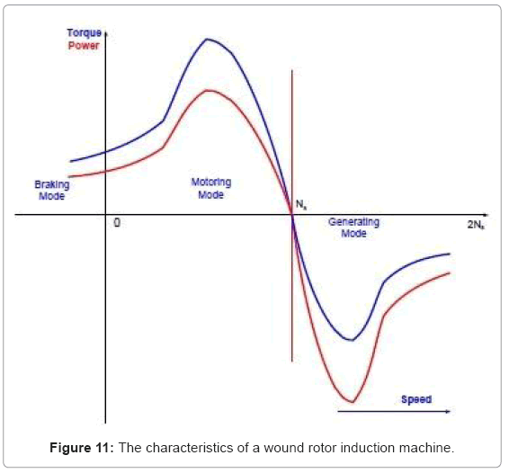
Figure 11: The characteristics of a wound rotor induction machine.
As an alternative, a wound rotor induction machine is also used as an IG. In this case, pitch or mechanical control of blades is avoided (Figure 12). However, a Wound Rotor Induction Generator (WRIG) system requires a grid-tied inverter which is quite costlier.
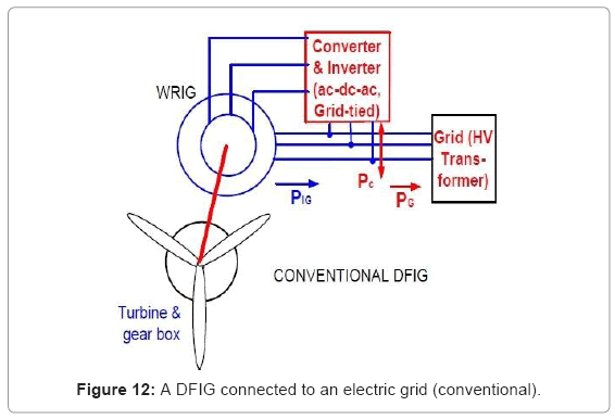
Figure 12: A DFIG connected to an electric grid (conventional).
Proposed Schemes
Recently the performance of wound-rotor induction motor has been greatly enhanced by combination of input voltage control and rotor resistance control simultaneously [9,10]. In the proposed work this technique is extended for IG with only rotor resistance control (Figures 13 and 14). The ac regulator is used only for soft starting. Here, the cost of controller reduces drastically due to simple control technique and due to the absence of a costly grid-tie inverter.
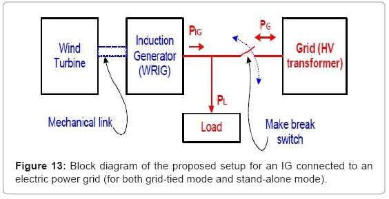
Figure 13: Block diagram of the proposed setup for an IG connected to an electric power grid (for both grid-tied mode and stand-alone mode).
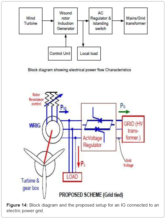
Figure 14: Block diagram and the proposed setup for an IG connected to an electric power grid.
Here, instead of using converter and grid-tied inverter at the rotor side, for feeding power to the grid (like static Scherbius drive of DFIG [11]), simple external rotor resistance control is employed as shown in Figure 14. The characteristics of IG are matched with the characteristics of wind turbines (red thick line) as shown in Figure 15. The speedtorque characteristics of the IG are adjusted with the help of slip power control. As the wind speed increases, the external rotor resistance is increased which shifts the torque-speed characteristics of IG and it matches with the torque speed characteristics of wind turbine. Now for any wind speed, a pre-calculated external resistance is added in the rotor circuit. It may be noted that at low speed, less external rotor resistance is added and at high wind speed, a large external rotor resistance is added which increases the rotor circuit loss. However, simultaneously at higher speed, the higher torque causes higher current and at that condition the efficiency of machine is also high (inset of Figure 15). Hence throughout the range of speed variation the rotor loss is not significantly high. Thus a simple and cheap external rotor resistance control method offers effective control.
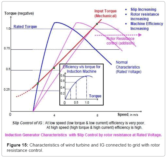
Figure 15: Characteristics of wind turbine and IG connected to grid with rotor resistance control.
In case of non-availability of grid connection, grid failure or black out, the above mentioned scheme cannot operate and the system cannot feed power to grid [12]. Thus, the same Wound Rotor Induction Generator (WRIG) is also used as an alternator with dc excitation from rotor side which is used as a stand-alone or isolated IG as shown in Figure 16.
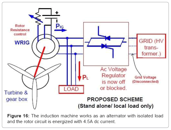
Figure 16: The induction machine works as an alternator with isolated load and the rotor circuit is energized with 4.5A dc current.
Experimental Results
Both the grid connected IG with rotor resistance control scheme and the stand-alone IG are tested practically in laboratory for a 3-phase, 400 V/420 V, 1.5 kW, star-connected WRIG. The prime mover (dc motor) speed is adjusted such that its speed is higher than the synchronous speed of IG. The Table 1 shows the variation of power flow or transmission from WRIG to grid at different speed. In case of grid failure or load shading condition, the power transmission to grid is not possible. Thus power cannot be fed to grid. The scheme shown in Figure 16 is used to make the wound rotor induction machine to act as an independent ac generator or an alternator which supplies power to an isolated load and works as a stand-alone power supply. Table 2 shows the experimental result at this condition.
| Rotor resistance (Rex in Ω) | Speed (N in rpm) | Grid voltage (in V) | Line or grid current (in A) | Input power (mech.) (in W) | Output power to grid (inW) |
| 0 | 1005 | 400 | 2.34 | 360 | 240 |
| 5 | 1053 | 400 | 2.48 | 544 | 296 |
| 10 | 1122 | 400 | 2.50 | 845 | 384 |
Table 1: Power of WRIG fed to grid.
| Rotor resistance (Rex in Ω) | Speed, (N in rpm) | Grid voltage (in V) | Line or grid current (in A) | Out power from IG (in Watt) |
| 0 | 1060 | 335 | 0.1 | 58 |
| 0 | 1160 | 348 | 0.5 | 301 |
| 0 | 1260 | 339 | 0.7 | 411 |
Table 2: WRIG supplying power to isolated load.
Conclusion
In this paper, instead of the harnessing the wind energy at highly potential wind sites, it is proposed to harness wind energy where the pollution is high and the average wind speed is low. For this purpose, Ganges river basin of North India is selected. Moreover, isolated locations and potential wind energy pockets are also considered which are not found by satellite mapping due to low resolution as well as due to mapping techniques. The satellite mapping of Ganges basin shows an average wind speed of less than 4 m/s whereas even in the month of April (calm month) it was found about 5 m/s at the bank of river at selected place. Also it is found practically that at the top of a slope at selected places the wind speed accelerates. Thus, the wind energy can be harnessed from such places which areas are otherwise not considered suitable for harnessing the wind energy. For this purpose, a simple and low cost WRIG based grid-tied system is proposed to feed, even low wind power to grid. Similarly, in case of grid failure or load shading condition, the same WRIG also works as stand-alone generator supplying power to local loads. Both systems are cheap and tested successfully.
In this way, the energy can be harnessed substantially, even at low wind area and significant amount of burning of fossil fuel can be saved which ultimately causes the environment pollution and the climate change. The landscape of Central Brazil also matches with the Ganges basin (Figure 17) with high terrine in southern part and where the wind speed is low (blue area). Therefore, potential wind site can be explored for Brazil using the same proposed method.
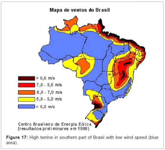
Figure 17: High terrine in southern part of Brasil with low wind speed (blue area).
References
- Ahmed S (2010) Wind Energy: Theory and Practice, Prentice-Hall of India, New Delhi, India.
- http://cleantechindia.wordpress.com/2008/07/16/indias-electricity-transmission-and-distribution-losses/
- Singh B (1993) Induction generators–a prospective. Electric Machines and Power Systems 23: 163-177.
- Bansal RC, Bhatti TS, Kothari DP (2003) Bibliography on the application of induction generators in non-conventional energy systems. IEEE Trans on Energy conversion 18: 433-439.
- Ashfaq H, Jamil Asghar MS (2003) Speed control of wound rotor induction motors by ac regulator based optimum voltage control. Proc of International conference on Power Electronics and Drive Systems (PEDS) 2:1037-1040.
- Ashfaq H, Jamil Asghar MS (2005) Optimum input volt-ampere control of three-phase induction motors connected to distributed generating systems. Proc of IEEE International Conference on Power Electronics and Drive Systems (PEDS) 1: 486-488.
- Dubey GK (2002) Fundamental of Electrical Drives. (2ndedn) Narosa Publishing House, New Delhi, India.
- Murthy SS, Singh BP, Nagamani C, Satayanarayana KVV (1988) Studies on the use of conventional induction motors as self-excited induction generators. IEEE Trans on Energy conversion 3: 842-848.
Citation: Khan KF, Arif SJ, Asghar MSJ (2013) Harnessing Low Power Wind Energy from Riverine and Isolated Potential Pockets using Wound Rotor Induction Machines. J Earth Sci Climat Change S12: 005.
Copyright: ©2013 Khan KF, et al. This is an open-access article distributed under the terms of the Creative Commons Attribution License, which permits unrestricted use, distribution, and reproduction in any medium, provided the original author and source are credited.
Select your language of interest to view the total content in your interested language
Share This Article
Recommended Journals
Open Access Journals
Article Usage
- Total views: 17935
- [From(publication date): 0-2013 - Aug 17, 2025]
- Breakdown by view type
- HTML page views: 13177
- PDF downloads: 4758